The Relationship Between the Altitude of the Standard Atmosphere and Air Temperature and Pressure

The Relationship Between the Altitude of the Standard Atmosphere and Air Temperature and Pressure

The standard atmosphere referred to here refers to the "1964, ICAO Standard atmosphere" adopted by the International Civil Aviation Organization. Below an altitude of 32 km, it is the same as "1976, U.S. standard atmosphere". Changes in air temperature near the surface (below 32 km) are:

Ground: The air temperature is 15.0℃, the air pressure P=1013.25mb= 0.101325MPa

Temperature change rate from ground to elevation 11 km: -6.5 ℃/ km

On the 11km interface:

The air temperature is -56.5 ℃ and the air pressure P=226.32mb

Temperature change rate at elevations of 11-20 km: 0.0℃/ km

Temperature change rate at altitude 20-32 km: +1.0/ km

The following table lists the temperature and pressure values of the standard atmosphere at different altitudes. In the table, "gpm" is the altitude meter, and its negative sign represents the altitude

Gpm

Temperature℃

Atmospheric pressure(mb)

Gpm

Temperature℃

Atmospheric pressure(mb)

Gpm

Temperature℃

Atmospheric pressure(mb)

-400

17.6

1062.2

4800

-16.2

554.8

10000

-50.0

264.4

-200

16.3

1037.5

5000

-17.5

540.2

10200

-51.3

256.4

0

15.0

1013.3

5200

-18.8

525.9

10400

-52.6

248.6

200

13.7

989.5

5400

-20.1

511.9

10600

-53.9

241.0

400

12.4

966.1

5600

-21.4

498.3

10800

-55.2

233.6

600

11.1

943.2

5800

-22.7

484.9

11000

-56.5

226.3

800

9.8

920.8

6000

-24.0

471.8

11500

-56.5

209.2

1000

8.5

898.7

6200

-25.3

459.0

12000

-56.5

193.3

1200

7.2

877.2

6400

-26.6

446.5

12500

-56.5

178.7

1400

5.9

856.0

6600

-27.9

434.3

13000

-56.5

165.1

1600

4.6

835.2

6800

-29.2

422.3

13500

-56.5

152.6

1800

3.3

814.9

7000

-30.5

410.6

14000

-56.5

141.0

2000

2.0

795.0

7200

-31.8

399.2

14500

-56.5

130.3

2200

0.7

775.4

7400

-33.1

388.0

15000

-56.5

120.5

2400

-0.6

756.3

7600

-34.4

377.1

15500

-56.5

111.3

2600

-1.9

737.5

7800

-35.7

366.4

16000

-56.5

102.9

2800

-3.2

719.1

8000

-37.0

356.0

17000

-56.5

87.9

3000

-4.5

701.1

8200

-38.3

345.8

18000

-56.5

75.0

3200

-5.8

683.4

8400

-39.6

335.9

19000

-56.5

64.1

3400

-7.1

666.2

8600

-40.9

326.2

20000

-56.5

54.7

3600

-8.4

649.2

8800

-42.2

316.7

22000

-54.5

40.0

3800

-9.7

632.6

9000

-43.5

307.4

24000

-52.5

29.3

4000

-11.0

616.4

9200

-44.8

298.4

26000

-50.5

21.5

4200

-12.3

600.5

9400

-46.1

289.6

28000

-48.5

15.9

4400

-13.6

584.9

9600

-47.4

281.0

30000

-46.5

11.7

4600

-14.9

569.7

9800

-48.7

272.6

32000

-44.5

8.7

Unit conversion relation

1mbar=100Pa=0.1KPa=0.0001 Mpa

1ft=0.3048m=304.8mm

55000ft*0.3048=16764m

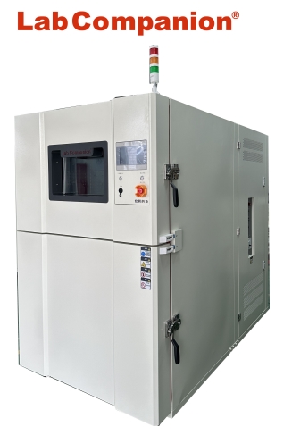
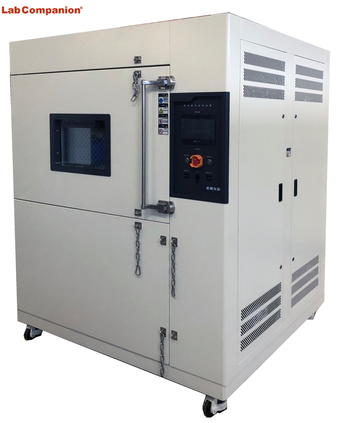
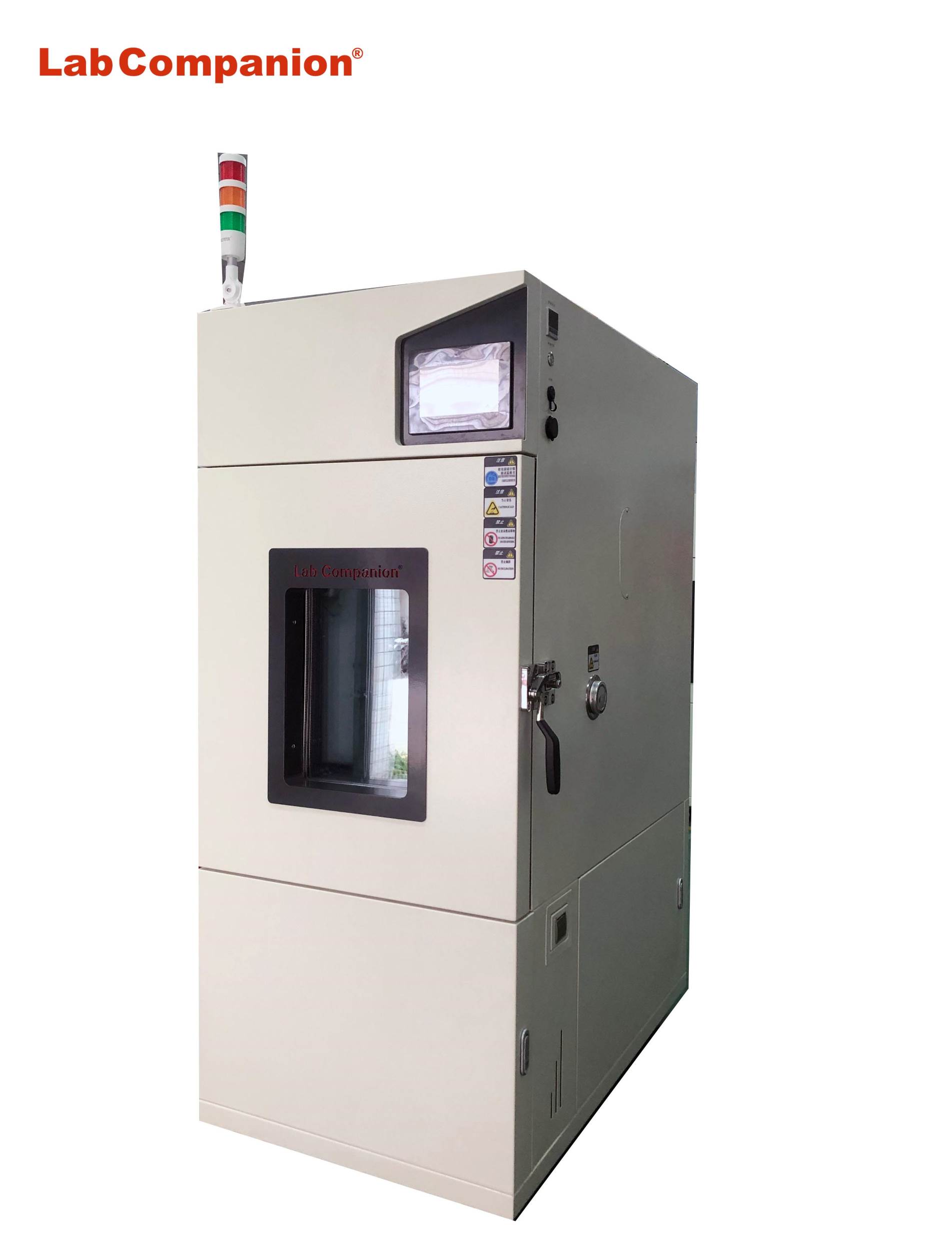
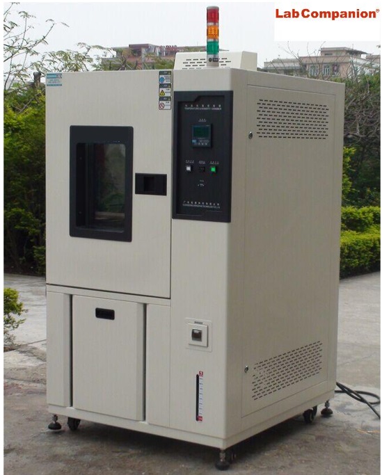
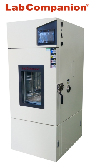
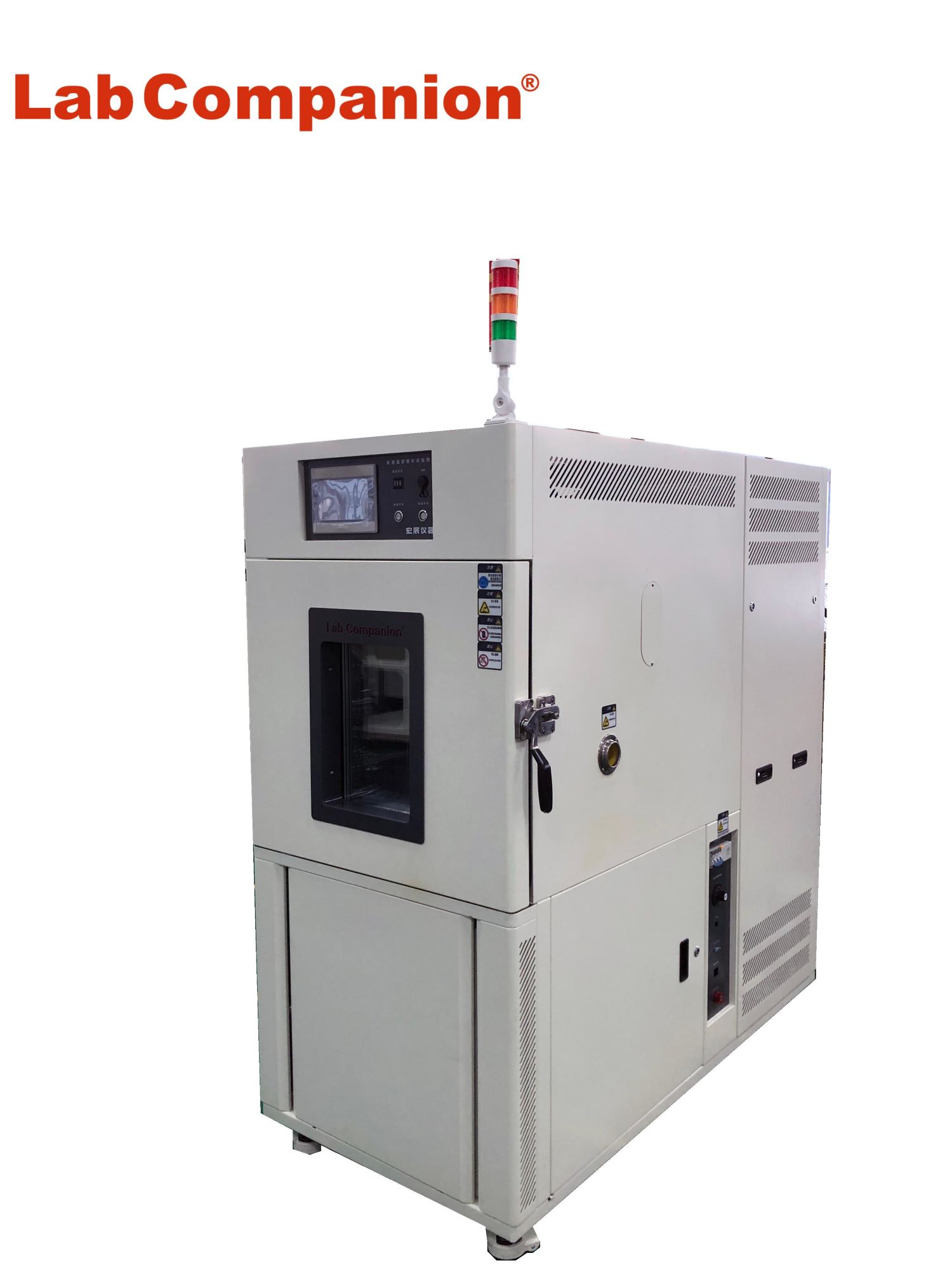
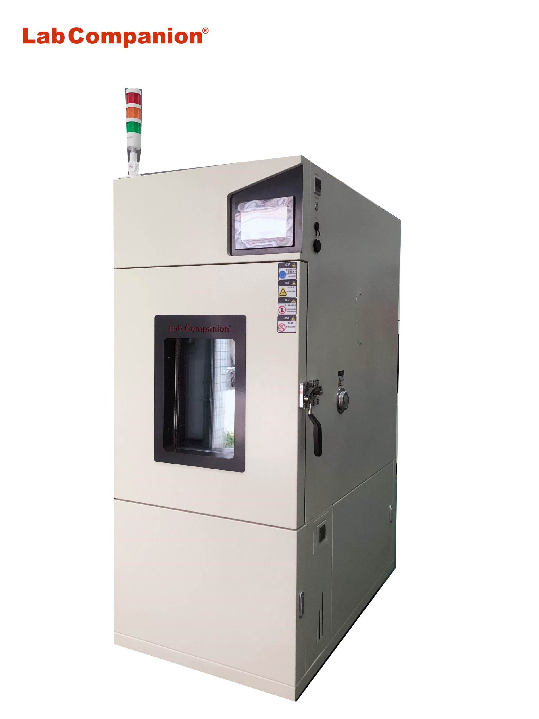
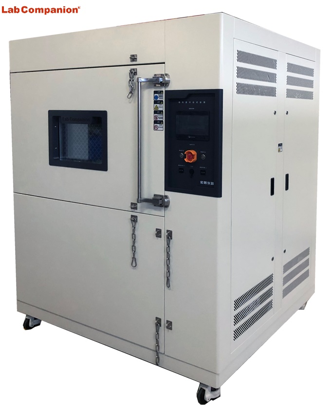
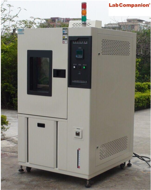
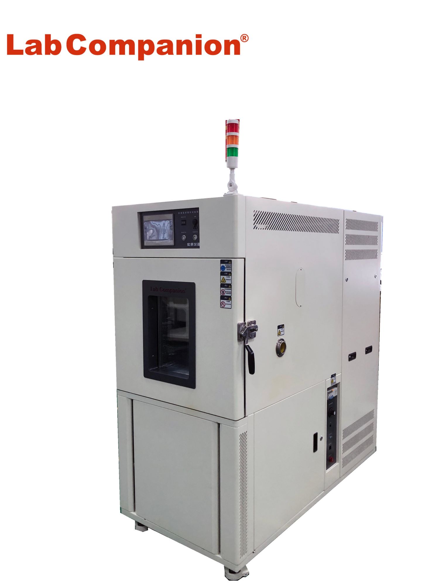
Lab Companion focused on the production of reliability environmental test equipment for 19 years, successfully helped 18,000 enterprises to test the reliability and environmental performance of products and materials.

The main products are: high temperature test chamber, high and low temperature and humidity test chamber, walk-in environmental test chamber, rapid temperature cycling test chamber, thermal shock test chamber, high and low temperature low pressure test chamber, vibration of the comprehensive chamber and other test equipment manufacturing solutions to help enterprises R & D bigger and stronger!

If you need to know more about the products of the environmental test chamber, you can search the official website of "Lab Companion", feel free to contact us for consultation, we can provide you with one-on-one professional technical advice and guidance.

Thin Film Solar Cell

Thin Film Solar Cell

Thin film solar cell is a kind of solar cell manufactured by thin film technology, which has the advantages of low cost, thin thickness, light weight, flexibility and bendability. It is usually made of semiconductor materials such as copper indium gallium selenide (CIGS), cadmium telluride (CdTe), amorphous silicon, gallium arsenide (GaAs), etc. These materials have high photoelectric conversion efficiency and can generate electricity under low light conditions.

Thin film solar cells can be used in inexpensive glass, plastic, ceramics, graphite, metal sheet and other different materials as substrates to manufacture, forming a film thickness that can generate voltage only a few μm, so the amount of raw materials can be significantly reduced than silicon wafer solar cells under the same light receiving area (thickness can be lower than silicon wafer solar cells more than 90%). At present, the conversion efficiency of up to 13%, thin film solar cells are not only suitable for flat structure, because of its flexibility can also be made into non-plane structure, has a wide range of application prospects, can be combined with buildings or become a part of the building body.

Application of thin film solar cell product:

Translucent solar cell modules: Building Integrated Solar Energy Applications (BIPV)

Application of thin film solar energy: portable folding rechargeable power supply, military, travel

Applications of thin film solar modules: roofing, building integration, remote power supply, defense

Features of thin film solar cells:

1. Less power loss under the same shielding area (good power generation under weak light)

2. The loss of power under the same illumination is less than that of wafer solar cells

3. Better power temperature coefficient

4. Better light transmission

5. High cumulative power generation

6. Only a small amount of silicon is needed

7. There is no internal circuit short circuit problem (the connection has been built in the series battery manufacturing)

8. Thinner than wafer solar cells

9. Material supply is secure

10. Integrated use with building materials (BIPV)

Solar cell thickness comparison:

Crystalline silicon (200 ~ 350μm), amorphous film (0.5μm)

Types of thin film solar cells:

Amorphus Silicon (a-Si), Nanocrystalline Silicon (nc-Si), Microcrystalline Silicon, mc-Si), compound semiconductors II-IV [CdS, CdTe(cadmium telluride), CuInSe2], Dye Sensitized Solar cells, Organic/polymer solar cells, CIGS (Copper indium selenide)... Etc.

Thin-film solar module structure diagram:

Thin film solar module is composed of glass substrate, metal layer, transparent conductive layer, electrical function box, adhesive material, semiconductor layer... And so on.

Reliability test specification for thin film solar cells:

IEC61646(Thin-film solar photoelectric module test standard), CNS15115(thin-film silicon onshore solar photoelectric module design validation and type approval)

Temperature & humidity test chamber of Lab Companion

Temperature & humidity test chamber series, passed the CE certification, offer 34L, 64L, 100L, 180L, 340L, 600L, 1000L, 1500L and other volume models to meet the needs of different customers. In design, they use environment-friendly refrigerant and high-performance refrigeration system, parts and components are used in the international famous brand.

Temperature & humidity test chamber

How to maintain the slurry pump on a daily basis?


The following is the first part of the daily operation and maintenance of slurry pumps: tart-up and shutdown:

Preparations Before Start-up:

Check whether the connecting bolts and foundation bolts of the pump are loose.

Check whether the piping connection is proper and whether the centers of the pump and the driver are aligned. For pumps handling high-temperature or low-temperature liquids, the expansion and contraction of the piping may cause shaft misalignment, seizure, etc. Therefore, flexible pipe joints, etc., should be used.

Direct coupling and alignment. For small-sized pumps handling normal-temperature liquids, there is no problem in aligning the pump and the motor when the pump is stopped. However, for large-sized pumps handling high-temperature liquids, there is a large difference in the shaft center during operation and stoppage. To achieve correct alignment, generally heat to the operating temperature or stop the pump after the operation and quickly re-align to ensure that the shaft centers of both rotating parts are the same and avoid vibration and pump seizure.

Clean the piping. Before operation, the piping must be cleaned first to remove foreign objects, welding slag, etc. from the piping. Do not let foreign objects or welding slag fall into the pump body. Install pressure gauges before and after the strainer in the suction pipe to monitor the clogging of the strainer during operation.

Barring. Remove the coupling before start-up, turn the rotor by hand to observe whether there are any abnormal phenomena, and conduct a separate test run of the motor to check whether its rotation direction is the same as that of the pump. By rotating the coupling by hand, it can be found whether there are foreign objects between the impeller and the casing inside the pump. The barring should be even in weight, and there should be no abnormal noise inside the pump.

Start the oil pump and check whether the bearing lubrication is good.

Priming the pump. Fill the pump chamber with liquid before start-up to discharge air, liquefied gas, and steam from the suction pipe and the pump body.

Start-up:

The idle operation must be avoided. At the same time, open the suction valve, and close the discharge valve and each discharge hole.

Open the cooling water supply valve for the bearings.

If the stuffing box has a water jacket, open the cooling water supply valve of the stuffing box.

If the pump handling high-temperature liquid has not reached the working temperature, open the preheating valve, and close this valve after the pump is preheated.

If the pump is equipped with a liquid-sealing device, open the valve of the liquid-sealing system.

If equipped with an overheating device, open the bypass valve of the self-circulation system.

Start the motor.

When the pump flow increases and overheating is no longer possible, close the valve of the self-circulation system.

If the pump must be started with the check valve closed and the outlet gate valve open, the start-up steps are basically the same as the above method, except that the outlet gate valve should be opened for a period of time before the motor is started.

Gradually open the discharge valve.

Shutdown:

Open the valve on the self-circulation system.

Close the discharge valve.

Stop the motor.

If it is necessary to maintain the working temperature of the pump, open the preheating valve.

Close the cooling water supply valves of the bearings and the stuffing box.

If liquid-sealing is not required during the shutdown, close the liquid-sealing valve.

If it is a special pump device requirement or when the pump is opened for inspection, close the suction valve, and open the vent hole and various discharge holes.

Usually, the start-up and shutdown steps specified for turbine-driven pumps are basically the same as those for motor-driven pumps. Turbines have discharge valves, various drain holes, and sealing devices, which must be opened or closed before and after operation. In addition, turbines generally require preheating before start-up. Some turbines in the system are required to be started at any time, so barring operation is required. Therefore, the operator should operate according to the relevant regulations on the start-up and shutdown steps of the turbine provided by the turbine manufacturer.

Maintenance During Shutdown For standby pumps at the chemical plant site, when the in-use pump fails, they should be able to be switched over in time and put into normal operation to ensure that the chemical production process is not interrupted. This requires the maintenance of the standby pumps to keep them in good condition during the standby and shutdown period. Especially for standby pumps with interlock and automatic switching, their inlet and outlet valves are open, and the pumps are filled with the medium to be transported. As long as the driver rotates, they can start working immediately.

For standby pumps during the shutdown period, the quality and quantity of the lubricant should be checked frequently. The pump body and the medium inside the pump that needs to be heated and insulated should be heated and insulated. To prevent the rotor from bending due to its own weight and to prevent the shaft from adhering to the bearings and causing start-up difficulties, the standby pumps should be barring regularly.

For pumps that have been shut down for a long time, open the plugs on the pump body to drain the liquid inside the pump to avoid damage to the pump body due to cold weather. If necessary, open the pump body, clean the internal parts, and apply anti-rust oil. For pumps that have been shut down for a long time, whether they are on-site or in the warehouse, they should be barring regularly.

For details of the first part, please refer to the next blog post.

Maintenance of slurry pumps during operation.

Lubrication: During the operation of a slurry pump, the possible intrusion of the conveyed medium, water, and other substances into the oil tank may affect the pump's normal operation. Therefore, it is necessary to check the quality and oil level of the lubricant frequently. The quality of the lubricant can be observed with the naked eye and analyzed by regular sampling. The amount of lubricating oil can be seen from the oil level mark.

For a new pump, the oil should be changed once after one week of operation. For a pump with replaced bearings during overhaul, the oil should also be changed. Because foreign substances enter the oil during the running-in of the new bearings and shafts, the oil must be changed. Thereafter, the oil should be changed once every quarter. The lubricating grease and lubricating oil used for chemical pumps should meet quality requirements. Tables 2-8 and 2-9 show the commonly used lubricating grease and lubricating oil for slurry pumps.

Vibration: During the operation of the pump, due to reasons such as poor quality of spare parts and maintenance, improper operation, or pipeline vibration, vibration often occurs. If the vibration exceeds the allowable value, the pump should be shut down for maintenance to prevent damage to the machine. Table 2-10 shows the allowable range of vibration values for slurry pumps.

Bearing temperature rise: During the operation of the pump, if the bearing temperature rises rapidly and after the temperature rise stabilizes, the bearing temperature is too high, which indicates that there are problems in the manufacturing or installation quality of the bearing; or the quality, quantity, or lubrication method of the bearing lubricating oil (grease) does not meet the requirements. If not dealt with in time, the bearing is in danger of being burned out. The allowable temperature for slurry pump bearings is <65°C for sliding bearings; and <70°C for rolling bearings. This allowable value refers to the allowable range of bearing temperature after running for a period of time. For a newly replaced bearing, at the initial stage of operation, the bearing temperature will rise relatively high. After running for a period of time, the temperature will drop somewhat and stabilize at a certain value.

The operating performance of slurry pump: During the operation of the pump, if there is no change in the liquid source and the opening degree of the valves on the inlet and outlet pipelines remains unchanged, but the flow rate or inlet and outlet pressure changes, it indicates that there is a fault in the pump or pipeline. The cause should be quickly identified and eliminated in time, otherwise, adverse consequences will be caused.

The size of the system resistance can be achieved by adjusting the opening degree of the inlet and outlet valves of the pump. For a determined pump system, when the outlet valve is fully opened, the system resistance is the smallest, and the corresponding flow rate is the largest, the head is the smallest, and the power is the largest. When the outlet valve is completely closed, the system resistance reaches a maximum value. At this time, the flow rate is zero, the head is the largest (a finite value), and the power is the smallest.

From this, the following points can be summarized:

When starting a slurry pump, in order to avoid overloading the prime mover, the outlet valve should be closed first and then opened slowly after the pump is started. In this way, it can avoid the superposition of the large starting load of the prime mover and the high power required by the pump when the outlet valve is fully opened, which may cause overloading of the prime mover.

As long as the pump chamber is filled with liquid (to avoid dry friction of the sealing ring, shaft seal, etc.), the slurry pump is allowed to operate for a short time when the outlet valve is closed. Except for the rapid temperature rise of the limited liquid in the pump chamber under the action of the rotating impeller, which has some adverse effects on the pump, there is no adverse effect on the prime mover. At this time, the load on the prime mover is the lightest.

During operation, any set of flow rates and heads within the performance range of the slurry pump can be obtained by adjusting the opening degree of the outlet valve. However, when the pump operates at the design operating point, its efficiency is the highest; the farther away from the design operating point, the lower the efficiency.

Unit sound: The sounds emitted by the pump during operation are some normal and some abnormal. For abnormal sounds, find out the cause and eliminate it in time. The following are roughly the reasons for the abnormal sounds of the pump.

Reasons on the fluid side: For example, insufficient inlet flow of the slurry pump causes cavitation and emits noise; air accumulation in the pump outlet pipeline causes water hammer and emits an impact sound.

Reasons on the mechanical side: The bearing quality does not meet the requirements or is damaged; the clearance between the moving and stationary parts of the pump is inappropriate, causing friction; shaft bending causes internal friction; parts are damaged and fall off; foreign objects fall into the pump, etc.


For details of the first part, please refer to the previous blog post.

What are the common application fields of magnetic pumps?

Chemical Industry:

Transporting corrosive liquids: It can be used to transport strong acids such as hydrochloric acid, sulfuric acid, and nitric acid, as well as strong alkali solutions like sodium hydroxide. In the production process of various chemical fertilizers, fluorides, etc. in chemical production, magnetic pumps are also often used to transport relevant media. At this time, chemical-resistant magnetic pumps are required.

Transporting flammable and explosive liquids: Such as gasoline, methanol, toluene, and other organic solvents. Magnetic pumps have no mechanical seal and will not generate friction sparks, which can ensure the safety of the transportation process and reduce the risk of fire and explosion accidents. At this time, organic solvent transfer magnetic pumps are needed.

Participating in chemical reactions: In some chemical reactions that require the cyclic transportation of reaction liquids, magnetic pumps can stably provide power to ensure the smooth progress of the reaction, for example, in the cyclic process of gas-absorbing reaction liquid. At this time, stainless steel chemical process magnetic pumps are needed.

chemical resistant magnetic pump

Pharmaceutical Industry:

Liquid medicine transportation: It is used to transport various liquid medicines, slurries, biological drugs, etc. Its leak-free and pollution-free characteristics can ensure the purity and quality of drugs, and ensure the stability and safety of drugs, meeting the strict requirements of pharmaceutical production. At this time, sanitary magnetic drive centrifugal pumps are required.

Pharmaceutical equipment support: In some pharmaceutical equipment, such as washing machines, reactors, etc., magnetic pumps need to be used in conjunction with transport media to meet the fluid transportation requirements in the pharmaceutical process. At this time, stainless steel chemical process magnetic pumps are needed.

Food Industry:

 In the fields of food processing and beverage production, magnetic pumps can be used to transport food raw materials or finished products such as fruit juice, milk, and syrup. Since there are no leak-prone or liquid-contacting parts, it will not cause secondary pollution to food, can maintain the original taste and quality of food, and improve the food hygiene standard. At this time, sanitary magnetic drive centrifugal pumps are required.


Electronic Industry:

 It is mainly used to transport corrosive liquids, pure water, and other media. In the electronic production process, the purity and cleanliness of the media are required to be extremely high. Magnetic pumps have no seals, which can avoid liquid leakage and damage to electronic equipment, and can also meet the high requirements of the electronic industry for media. At this time, fluoroplastic anti-corrosion magnetic pumps are required.


Electroplating Industry: 

It is suitable for the transportation and cyclic filtration of various electroplating solutions, such as chrome-plating solutions, nickel-plating solutions, zinc-plating solutions, etc. Magnetic pumps can run stably in the harsh environment of the electroplating process, ensure the accurate transportation of electroplating solutions, and improve the efficiency and quality of electroplating production. At this time, polyvinylidene fluoride (PVDF) material magnetic-driven pumps are required.


Petrochemical Industry:

Crude oil transportation: In the process of oil exploration and transportation, crude oil and its associated media can be transported. Its good sealing and reliability can ensure the safety and efficiency of oil production. At this time, three-screw magnetic-driven pumps are required.


Refining process: In the refinery unit, it is used to transport various high-temperature, high-pressure, and corrosive media, such as transporting relevant liquids in the process of catalytic cracking, hydrocracking, etc. At this time, CQG - G series high-temperature and high-pressure magnetic pumps are required.


Mining Industry:

Metal smelting: It is used to transport electrolytes in the metal smelting process and wash the waste liquid generated during the smelting process, which helps to improve the efficiency and environmental protection of metal smelting. At this time, polyvinylidene fluoride (PVDF) material magnetic-driven pumps are required.


Mineral processing: In the mineral processing process, it can transport various slurries, acid solutions, and other media, providing fluid transportation support for each link of mining production. At this time, high-chromium alloy magnetic-driven pumps are required.

High chromium alloy magnetic driven pump

What are the sealing methods of centrifugal pumps?

The dynamic seal of a centrifugal pump is a sealing method that relies on the centrifugal force of rotating components, and it can be divided into two categories: back-blade seal and auxiliary impeller seal.


Back - blade seal:

(1) Structure: Blades are added to the rear cover plate of the impeller of the centrifugal pump, and these blades rotate in the opposite direction to the impeller. These blades are back-blades.

(2) Working principle: When the centrifugal pump is in operation, the rotation of the impeller drives the back blades to rotate together. The centrifugal force generated by the rotation of the back - blades will throw the liquid at the rear cover plate of the impeller to the outer periphery of the impeller, reducing the liquid pressure at the rear cover plate of the impeller and forming a low-pressure area. As a result, it is difficult for the high-pressure liquid at the impeller outlet to leak through the gap between the impeller and the pump casing to the low-pressure area, thus achieving the sealing effect.

(3) Advantages: The structure is relatively simple, no additional complex devices are required, and the cost is low; it can balance the axial force of the centrifugal pump to a certain extent, reduce axial movement, and improve the operation stability of the pump.

(4) Disadvantages: The sealing effect is relatively weak, and it may not be suitable for some occasions with very high sealing requirements; the presence of back-blades will increase the frictional resistance of the impeller, resulting in a slight reduction in the pump's efficiency.


Auxiliary impeller seal:

(1) Structure: It usually consists of an auxiliary impeller, auxiliary blades (also called back-blades), fixed guide vanes, and a shutdown sealing device. The auxiliary impeller is a small centrifugal pump impeller, which rotates coaxially with the working impeller of the centrifugal pump.

(2) Working principle: During operation, the liquid leaked from the working impeller of the centrifugal pump flows to the auxiliary impeller. The centrifugal force generated by the rotation of the auxiliary impeller forms a pressure head, which can resist the high-pressure liquid at the outlet of the working impeller from leaking out, thereby achieving the sealing purpose. When the pump is shut down, the dynamic seal of the auxiliary impeller does not work. The liquid pressure inside the pump is small, and the liquid leaked to the auxiliary impeller is sealed by the shutdown sealing device. For example, three oil seals and one water-blocking ring are used for sealing.

(3) Advantages: The sealing effect is relatively good, and it is suitable for conveying media containing certain impurities because the influence of impurities on the auxiliary impeller is relatively small; during the operation process, the centrifugal force generated by the auxiliary impeller can also play a certain stirring role to prevent the precipitation of the medium.

(4) Disadvantages: The rotation of the auxiliary impeller consumes a certain amount of energy, which will increase the power consumption of the pump; the processing accuracy requirements of the auxiliary impeller are relatively high, and the manufacturing difficulty is relatively large.


The dynamic seals produced by Anhui Changyu Pump and Valve Manufacturing Co., Ltd. are all made of fiberglass - reinforced plastic. Due to the relatively low density of fiberglass - reinforced plastic, when the back - blades rotate, at the same rotational speed, their moment of inertia is relatively small. This means that during the starting and stopping processes, the back - blades need to overcome less inertial force and can reach a stable operating state or stop more quickly. From the perspective of the sealing principle, the fiberglass - reinforced plastic back - blades are stable in performance when the centrifugal force generated by rotation throws the liquid at the rear cover plate of the impeller to the outer periphery. Moreover, the good corrosion resistance of fiberglass - reinforced plastic can prevent changes in the blade surface caused by liquid corrosion, thereby maintaining the formation of a low - pressure area stably for a long time and ensuring the sealing effect. For example, in the working condition of transporting a mixed solution of acid, alkali, and salt with a certain concentration, the fiberglass - reinforced plastic back - blades can maintain the sealing performance more effectively compared with metal back - blades and reduce the situation of seal failure caused by corrosion.

mechanical seal


The mechanical seal of a centrifugal pump is a high-performance sealing method. The following is a detailed introduction:

Structural composition

(1) Rotating ring and stationary ring: The rotating ring rotates with the pump shaft, and the stationary ring is fixed on the pump body and remains stationary. They are the key sealing elements of the mechanical seal. They are usually paired with hard materials (such as tungsten carbide, ceramic, etc.) and soft materials (such as graphite, impregnated graphite, etc.). The end faces of these materials are finely ground with extremely high flatness. For example, in some high-temperature and high-pressure application scenarios, the combination of tungsten carbide and graphite is often used. Tungsten carbide has high hardness and good wear resistance, and graphite has good self-lubricating properties and chemical stability.

(2) Spring: The spring provides the axial pre - tightening force for the mechanical seal to ensure that the end faces of the rotating ring and the stationary ring are always in close contact during the operation of the centrifugal pump. There are various types of springs, including single-spring and multi-spring forms. The single-spring structure is simple, but the force is unevenly distributed; the multi-spring can make the force distribution more uniform and is suitable for high-speed centrifugal pumps.

(3) Sealing ring: It is used to seal the gaps between the rotating ring and the shaft, the stationary ring and the gland, etc., to prevent liquid from leaking from these parts. The material of the sealing ring is selected according to different working conditions. Common materials include rubber (such as nitrile rubber, fluorine rubber, etc.) and polytetrafluoroethylene. For example, when transporting acidic media, fluorine rubber sealing rings can be selected because of their good acid resistance.


Working principle

During the operation of the centrifugal pump, the spring force and the liquid pressure act on the rotating ring together, making the end faces of the rotating ring and the stationary ring closely contact to form an extremely thin liquid film. This liquid film has a sealing effect and can also lubricate and cool the end faces. Since the rotating ring rotates with the shaft and the stationary ring is fixed, the existence of the liquid film can reduce friction and wear when the two are in relative motion, when the pressure inside the pump changes, the change in liquid pressure will also affect the sealing force between the rotating ring and the stationary ring, thus ensuring the sealing performance under different working conditions.

Advantages

(1) Good sealing performance: The leakage of the mechanical seal is extremely small, which can effectively prevent the liquid inside the pump from leaking. It is very suitable for some occasions with strict leakage requirements (such as centrifugal pumps for transporting toxic, flammable, and explosive media).

(2) Long service life: The high-quality materials of the rotating ring and the stationary ring and the reasonable structural design enable the mechanical seal to operate stably for a long time under normal working conditions, reducing the trouble of frequent seal replacement.

(3) Adapt to various working conditions: It can adapt to complex working conditions such as high temperature (some mechanical seals can work in a high-temperature environment of several hundred degrees), high pressure (the pressure can reach several megapascals or even higher), and high speed (high - speed centrifugal pumps), and has good sealing effects for clean media and media containing a small amount of impurities.

(4) Low power loss: Since the liquid film between the rotating ring and the stationary ring plays a good lubricating role and the friction coefficient is small, compared with the packing seal, the power loss of the mechanical seal is lower, which is beneficial to improving the operation efficiency of the centrifugal pump.


Disadvantages

(1) Complex structure: The mechanical seal has many components, and the structure is relatively complex, with high requirements for design, manufacturing, and installation. For example, the parallelism of the end faces of the rotating ring and the stationary ring is strictly required, and a slight deviation during the installation process may affect the sealing performance.

(2) High cost: The high-quality materials of the rotating ring and the stationary ring are expensive. Coupled with the precision processing technology and complex assembly requirements, the cost of the mechanical seal is much higher than that of other sealing methods such as the packing seal.

(3) Sensitive to impurities: If the medium contains more solid impurities or particles, the impurities may enter between the end faces of the rotating ring and the stationary ring, scratching the sealing surface and causing the seal to fail. Therefore, there are certain requirements for the cleanliness of the medium.


The mechanical seals produced by Anhui Changyu Pump and Valve Manufacturing Co., Ltd. have good sealing performance, long service life, can adapt to various working conditions, low power loss, and high processing precision. With strict factory - out inspection, the superior performance of the mechanical seals is ensured.


What is a magnetic-drive pump?

Introduction

In the field of liquid transportation in modern industry, magnetic-drive pumps stand out with their unique designs and excellent performance. It is an innovative type of pump that utilizes the principle of magnetic coupling to achieve leak-free liquid transportation, providing an effective solution to the leakage problem of traditional pumps under special working conditions. It is widely used in industries such as chemical, pharmaceutical, and environmental protection, where high requirements for safety and sealing are imposed.


Structure of Magnetic Pumps

Pump Body And Impeller


Pump Body

The pump body is an important outer casing part of the magnetic drive pump. Its main function is to provide a stable flow passage and accommodation space for the liquid. The selection of its material is crucial and is usually determined according to the nature of the liquid being transported. For corrosive liquids, corrosion-resistant metal materials such as stainless steel and Hastelloy are generally used, or high-performance engineering plastics such as polyvinylidene fluoride (PVDF) are adopted. The designed shape and internal flow channel structure of the pump body are carefully optimized to ensure that the liquid can flow smoothly and efficiently during the flow process, reducing energy loss and turbulence.


Impeller

The impeller, as the core hydraulic component of the magnetic-drive pump, is directly related to the pump's performance. It is installed on the pump shaft and connected to the inner magnetic rotor. There are various types of impellers, and common ones include closed-type impellers, open-type impellers, and semi-open-type impellers. Closed-type impellers have high efficiency and stable flow, and are suitable for transporting clean liquids; open-type and semi - open - type impellers have better anti-clogging capabilities and are suitable for transporting liquids containing certain particulate impurities. During the rotation process, the impeller converts the mechanical energy input by the motor into the kinetic energy and pressure energy of the liquid, enabling the liquid to flow smoothly from the inlet to the outlet of the pump.


Magnetic Transmission Components


Inner Magnetic Rotor

The inner magnetic rotor is one of the key components of the magnetic transmission of the magnetic-driven pump. It is coaxially connected to the impeller. The inner magnetic rotor is usually made of high-strength, high - energy - product permanent magnetic materials, such as neodymium - iron - boron (NdFeB). These permanent magnetic materials can maintain a stable magnetic field strength for a long time, ensuring the reliability of magnetic transmission. The structural design of the inner magnetic rotor needs to consider the uniformity of the magnetic field distribution and the coupling effect with the outer magnetic rotor. At the same time, it also needs to take into account its corrosion resistance and mechanical strength in the liquid, because it is directly in contact with the transported liquid or adjacent to it through the isolation sleeve.


Outer Magnetic Rotor

The outer magnetic rotor is installed on the motor shaft, corresponding to the inner magnetic rotor, and separated by an isolation sleeve. The outer magnetic rotor is also made of permanent magnetic materials, and its magnetic field strength and pole distribution match those of the inner magnetic rotor. When the motor drives the outer magnetic rotor to rotate, the generated rotating magnetic field can penetrate the isolation sleeve and act on the inner magnetic rotor, driving the inner magnetic rotor to rotate synchronously. The design of the outer magnetic rotor needs to consider the firmness of the connection with the motor shaft and the concentricity to ensure the smoothness and high efficiency of the magnetic transmission.


acid transfer magnetic pump

Isolation Sleeve

The isolation sleeve is the core guarantee for the magnetic-drive pump to achieve leak-free operation. It is located between the inner and outer magnetic rotors and completely isolates the liquid inside the pump from the outside. The selection of the material and thickness of the isolation sleeve is very important. On the one hand, it must have good corrosion resistance to resist the erosion of the transported liquid; on the other hand, it must have sufficient strength to withstand the internal and external pressure differences. Common isolation sleeve materials include metals (such as stainless steel) and non-metals (such as ceramics, glass-fiber-reinforced plastics, etc.). Metal isolation sleeves will generate eddy current losses in the magnetic field, affecting the magnetic transmission efficiency, but have high strength; non-metal isolation sleeves have no eddy current losses, but their strength and high-temperature resistance may be relatively weak. Therefore, a reasonable selection needs to be made according to the specific working conditions.


Bearing and Support Structure


Sliding Bearing

Inside the magnetic-drive pump, the pump shaft is usually supported by sliding bearings. Since the transported liquid often has poor lubricity and may even be corrosive, the materials of the sliding bearings must have good wear resistance and self-lubricating properties. Commonly used materials include silicon carbide ceramics, graphite, and filled polytetrafluoroethylene. These materials can reduce wear under harsh lubrication conditions, ensure the stable rotation of the pump shaft, and extend the service life of the bearings. The design of the sliding bearings also needs to consider the fitting accuracy of the pump shaft and the load-bearing capacity to adapt to the load requirements under different working conditions.


Rolling Bearing

Rolling bearings are mainly used to support the outer shaft of the pump, the part connected to the motor. It can effectively reduce the frictional resistance during the rotation process and improve transmission efficiency. The selection of rolling bearings needs to consider factors such as load-bearing capacity, speed range, and lubrication method. Generally, rolling bearings with good sealing performance are used, and appropriate lubricating grease is selected according to the actual working environment to ensure their long-term stable operation. In addition, there are support structures such as connecting frames, whose functions are to ensure the stable relative position between the pump body and the motor, ensure the coaxiality and perpendicularity of each component during the operation of the magnetic-drive pump, and reduce vibration and noise.


Working Principle of Magnetic-Drive Pumps

After the motor is started, the motor shaft drives the outer magnetic rotor to start rotating. The rotating magnetic field generated by the outer magnetic rotor penetrates the isolation sleeve and acts on the inner magnetic rotor. Due to the interaction of the magnetic fields, the inner magnetic rotor rotates synchronously within the isolation sleeve. The inner magnetic rotor is connected to the impeller, so the impeller also rotates. Under the action of the impeller's rotation, the liquid is sucked in from the inlet of the pump and enters between the blades of the impeller. With the high-speed rotation of the impeller, the liquid obtains kinetic energy and is thrown towards the edge of the pump body under the action of centrifugal force. In the flow passage formed by the pump body and the impeller, the kinetic energy of the liquid is gradually converted into pressure energy, and the liquid with increased pressure is discharged through the outlet of the pump. During the whole process, due to the action of magnetic transmission, the liquid inside the pump is completely isolated from the outside, and there is no leakage channel of the mechanical seal of traditional pumps, thus realizing leak-free transportation.


Characteristics of Magnetic Pumps


Leak - free Characteristic

The greatest advantage of the magnetic-drive pump lies in its leak-free performance. In many industrial occasions, such as the transportation of flammable, explosive, toxic, and harmful liquids in chemical production, or the transportation of liquid medicine with extremely high purity requirements in the pharmaceutical industry, the seal leakage of traditional pumps may cause serious safety accidents and quality problems. However, the magnetic-drive pump completely encloses the liquid inside the pump body through magnetic coupling transmission, eliminating the medium leakage caused by seal failure and effectively ensuring the safety of the production environment and product quality.


Safety and Reliability


Operational Stability

The structural design of the magnetic-drive pump makes it have high stability during the operation process. Since there is no friction and wear at the mechanical seal and the resulting vibration and noise, the magnetic-drive pump operates more smoothly. At the same time, the magnetic coupling can maintain stable transmission during normal operation. When encountering an overload situation, such as impeller blockage or jamming, the outer magnetic rotor, and the inner magnetic rotor can relatively slip, avoiding damage to the motor and transmission components due to excessive torque, playing a certain overload protection role.


Reducing the Risk of Failure

Without the problem of easy damage of traditional mechanical seals, the risk of failure of the magnetic-drive pump is greatly reduced. Mechanical seals are prone to leakage due to wear, aging, and corrosion during long-term operation, while the magnetic transmission components of the magnetic-drive pump have a long service life, reducing sudden failures caused by seal damage, improving the reliability and continuous operation time of the equipment, and reducing the impact of maintenance costs and downtime on production.


Simple Maintenance

Since the magnetic-drive pump has no mechanical seals, packing seals, and other components that need to be regularly replaced and maintained, its maintenance work is relatively simple. This not only reduces the workload of maintenance personnel but also reduces the maintenance cost. In addition, the structure of the magnetic-drive pump is relatively compact, and the number of parts is relatively small, which also makes it more convenient and faster to conduct maintenance and troubleshooting, further improving the maintainability of the equipment.

Magnetic Pump


Development Trends of Magnetic - Drive Pumps

With the continuous progress of science and technology, magnetic-drive pumps will develop towards higher performance and more intelligent directions in the future. In terms of materials, the research and development of new magnetic materials will further improve the magnetic transmission efficiency and reduce energy loss. At the same time, the improvement of isolation sleeve materials will make the isolation sleeve have high strength and high corrosion resistance while reducing the impact on magnetic transmission. In terms of design, optimizing the hydraulic design of the pump body and impeller will improve the efficiency and performance of the pump. In addition, with the development trend of industrial automation and intelligence, magnetic-drive pumps will be increasingly integrated into intelligent control systems, realizing functions such as remote monitoring, fault diagnosis, and automatic alarm, further improving the reliability and management efficiency in industrial production, and better meeting the strict requirements of modern industry for liquid transportation equipment.


Photovoltaic solar aluminum profiles

Photovoltaic solar aluminum profiles

Photovoltaic solar aluminum profiles

Aluminum profiles are recognized as an eco-friendly and highly durable material. Due to their lightweight, corrosion resistance, excellent thermal conductivity, high strength, and ease of transportation and installation, they are commonly used in the manufacturing of brackets and frames for photovoltaic (PV) modules. This specific type of aluminum profile, widely utilized in the solar energy sector, is referred to as photovoltaic aluminum profiles.

In an era where the scarcity of non-renewable energy sources like coal and oil poses significant challenges to global economic development, more countries are implementing "Solar Initiatives" to harness solar energy resources and seek new drivers for economic growth.

Solar energy photovoltaics are one of the seven key emerging industries prioritized for development in our country. The rapid growth in the photovoltaic power generation sector, both in China and internationally, has significantly increased the demand for aluminum profiles used in solar modules. China holds the largest installed capacity for photovoltaic power globally, with cumulative installed capacity reaching 39,261 MW in 2022, indicating a sustained growth trend. Analyzing the industrial chain: the upstream includes the production of aluminum metal, mainly involving bauxite, alumina, and electrolytic aluminum; the midstream focuses on processes like extrusion, aging, and surface treatment to manufacture industrial aluminum profiles for photovoltaics; while the downstream involves precision processing, turning aluminum profiles into photovoltaic frames and brackets.

As of 2022, the CR5 of China’s photovoltaic frame industry reached 48%, with leading enterprises capturing nearly half of the market share.

Photovoltaic aluminum alloy profiles are primarily used as frames for solar panels, providing essential support. They serve to fix and seal the solar cell components, enhance structural strength, and facilitate transportation and installation. Aluminum profiles account for approximately 90% of photovoltaic modules, constituting about 8-9% of total costs. Their replacement is challenging, but demand will continue to grow alongside the expansion of the renewable energy photovoltaic sector.

More countries are recognizing the importance of developing the photovoltaic industry, leading to a rising demand for photovoltaic aluminum profiles. At Huanan Heavy Industry, we place great emphasis on the production of photovoltaic materials. With continuous technological innovation in our aluminum extrusion machinery, our equipment has reached a high level of maturity in extruding photovoltaic aluminum profiles. For more information about our photovoltaic aluminum profile extrusion machines, please visit our website: https://www.huananmachine.com/. Feel free to contact us with any questions.


The process characteristics and advantages of aluminum extrusion molding

Aluminum extrusion machine

The process characteristics and advantages of aluminum extrusion molding

In recent years, driven by the demand for miniaturization and lightweight design across various industries, aluminum and its alloys have gained significant popularity due to their excellent malleability, high strength, corrosion resistance, and light weight. As a result, aluminum extrusion products have seen increasing use in fields such as construction, packaging, transportation, electronics, healthcare, and aerospace.


Definition of Aluminum Extrusion

Aluminum extrusion is a forming process where an aluminum alloy billet is placed in a die cavity (or extrusion chamber) and subjected to substantial pressure. This pressure causes the aluminum to undergo directional plastic deformation and flow through the die openings, creating profiles with desired cross-sectional shapes, dimensions, and specific mechanical properties.


Types of Aluminum Extrusion Processes

Aluminum extrusion can be classified into several types based on the metal flow direction relative to the die's motion:


Direct Extrusion: The metal flows in the same direction as the die's movement.

Indirect Extrusion: The metal flows in the opposite direction to the die's movement.

Compound Extrusion: Part of the metal flows in the same direction as the die movement, while the other part flows in the opposite direction.

Radial Extrusion: The metal flows at a 90-degree angle to the die's movement.

Key Features of the Aluminum Extrusion Process

The extrusion process places the metal under intense three-dimensional compressive stress, providing it with better plasticity compared to rolling or forging.

Extrusion allows the production of not only simple shapes (like rods and tubes) but also complex profiles.

It offers high flexibility, as changing a die can enable the production of different shapes, sizes, and types on the same equipment—resulting in a time-efficient and highly adaptable process.

Extruded products exhibit high dimensional precision, excellent surface quality, and improved material utilization.

The process enhances the mechanical properties of the metal.

With a relatively short process flow, extrusion allows the production of large, integrated components in a single step. It requires lower investment in equipment and dies, making it cost-effective.

Aluminum alloys are particularly suited for extrusion, supporting diverse extrusion processes and die structures.

Advantages of Aluminum Extrusion

Enhanced Deformation Capability: Aluminum in the extrusion zone undergoes strong triaxial compressive stress, optimizing its plasticity and allowing significant deformation.

High Product Quality: Extrusion improves the structure and mechanical properties of aluminum. After quenching and aging, extruded products achieve superior longitudinal strength (along the extrusion direction) compared to other processing methods. Extruded products also feature high dimensional accuracy and excellent surface finish.

Wide Product Range: Extrusion can produce simple profiles like tubes, bars, and wires, as well as intricate hollow and solid shapes. It also enables variable cross-sectional profiles that are difficult or impossible to create through other plastic forming methods.

Production Flexibility: Extrusion is highly adaptable, allowing for the production of different products on the same equipment simply by changing the die. This ease of tool change makes it a quick and efficient process.


Simple Process and Low Investment: Compared to other methods like piercing rolling or groove rolling, extrusion has a simpler production process, requires fewer pieces of equipment, and demands lower investment. Huananmachine is professional aluminum extrusion press machine manufacturer,get more details quickly.


A Guide to Selecting and Applying Desulfurization Pumps

What is a Desulfurization Pump?

A desulfurization pump is a specialized pump used in industrial desulfurization processes to handle corrosive and high-temperature fluids. These pumps are commonly used in flue gas desulfurization (FGD) systems of coal-fired power plants, steel plants, and the chemical industry. The primary function of a desulfurization pump is to transport desulfurization slurry from the absorption tower to other components, ensuring the smooth operation of the desulfurization process.

Types and Working Principles of Desulfurization Pumps

Desulfurization pumps can be classified based on their usage environment and the characteristics of the media they handle. The main types include:

  • Slurry pumps: Designed to transport slurry with high concentrations of solid particles and to withstand abrasive conditions.
  • Self-priming pumps: Equipped with self-priming capability, suitable for systems that require rapid startup.
  • Corrosion-resistant pumps: Made from high-corrosion-resistant materials such as stainless steel, alloys, or ceramics, to handle the acidic and corrosive fluids generated during flue gas desulfurization.

In terms of working principle, desulfurization pumps rely on the rotation of an impeller to drive the slurry. Centrifugal force is used to discharge the slurry from the pump body, completing the transport process.

Key Performance Indicators of Desulfurization Pumps

  • Corrosion resistance: As desulfurization processes involve corrosive substances like sulfuric acid and calcium sulfate, selecting the right material for the pump is critical. Common materials include high-nickel alloys and duplex stainless steel.
  • Wear resistance: The slurry often contains solid particles, which can wear down the pump over time. Therefore, the pump's design and materials must have high wear resistance.
  • Efficiency: To reduce energy consumption, desulfurization pumps need to maintain high efficiency. This is especially important in large-scale industrial desulfurization projects to save costs.
  • Reliability and stability: Desulfurization systems typically operate continuously, and pump failure can lead to system shutdowns. Therefore, desulfurization pumps must be highly reliable and stable, reducing maintenance costs.

Desulfurization Pumps

How to Select the Right Desulfurization Pump?

Selecting the right desulfurization pump is crucial, and the following key steps should be considered:

  • Understand process parameters: First, you need to determine the characteristics of the fluid in the desulfurization process, including temperature, concentration, corrosiveness, and abrasiveness. These factors influence the selection of pump materials and design.
  • Choose the right materials: Select the appropriate pump body material based on the corrosiveness of the media. For highly acidic media, high-alloy materials are recommended, while for strongly alkaline media, materials resistant to alkaline corrosion should be used.
  • Determine flow rate and head: Calculate the required flow rate and head based on the system's needs to ensure that the pump's performance meets process requirements.
  • Consider energy efficiency: Choose energy-efficient pumps that can help reduce long-term operating costs, while still meeting the basic performance requirements.

Daily Maintenance of Desulfurization Pumps

To ensure stable operation of desulfurization pumps, routine maintenance is essential:

  • Regularly inspect pump body and impeller wear: Especially when transporting high-concentration slurry, regularly check for wear on the impeller and pump casing, and replace severely worn components in a timely manner.
  • Monitor the sealing system: The sealing part of the desulfurization pump is often a vulnerable component. Regularly check the sealing performance to prevent slurry leakage.
  • Lubricate bearings regularly: Bearings are key components of the pump. Regularly apply lubricating oil to ensure smooth operation of the bearings.

Why Choose Changyu Pumps for Your Desulfurization Needs?

At Changyu Pumps, we are committed to delivering high-performance and highly reliable desulfurization pump solutions. Our pumps are made from advanced corrosion-resistant and wear-resistant materials, specifically designed to perform in harsh working environments. We offer comprehensive pre-sales selection guidance and post-sales maintenance services to ensure each desulfurization pump achieves optimal performance.