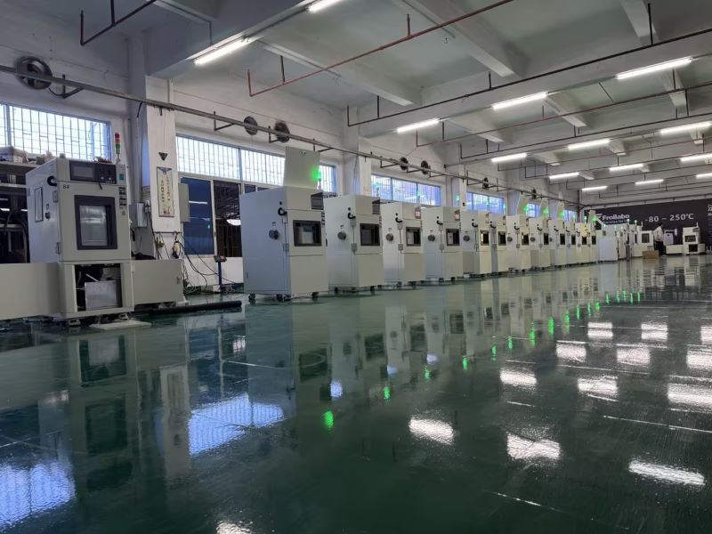
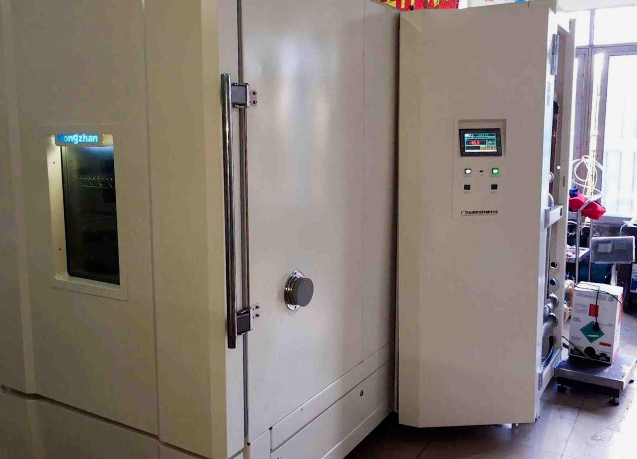
What is a Stability Chamber and How Does It Work?

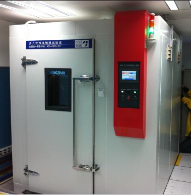
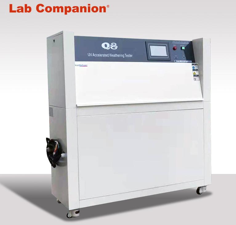
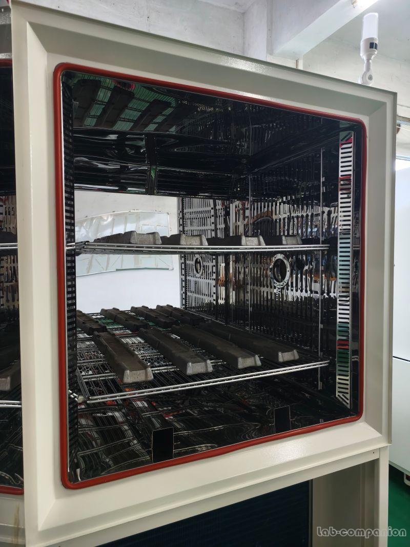
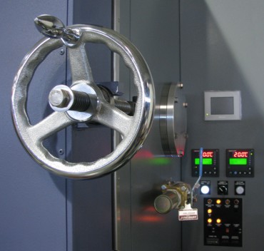
A Stability Chamber, also known as a Stability Test Chamber, is a specialized piece of equipment designed to create controlled environmental conditions for testing the stability and durability of products. These chambers are essential tools in industries such as pharmaceuticals, cosmetics, food and beverage, and electronics, ensuring that products meet regulatory and quality standards.


Functions of a Stability Chamber

The primary purpose of a Stability Chamber is to simulate various environmental conditions, such as temperature and humidity, over extended periods. This allows manufacturers to observe how their products react to environmental stressors like heat, cold, moisture, and light. Stability Chambers are equipped with advanced temperature and humidity control systems to maintain precise conditions, often following international guidelines like ICH Q1A for stability testing.

Key features include:

1.Temperature Control: Ranges typically from 10°C to 60°C.
2.Humidity Control: Adjustable levels between 20% to 95% relative humidity.
3.Uniformity: Ensures consistent conditions throughout the chamber.
4.Data Logging: Real-time monitoring and recording of testing conditions.

Applications of Stability Test Chambers

1.Pharmaceuticals: Conducting stability studies to determine drug shelf life and optimal storage conditions.
2.Food & Beverage: Testing packaging and product stability under varying conditions to ensure quality.
3.Cosmetics: Assessing formulations for durability against temperature and humidity changes.
4.Electronics: Simulating environmental conditions to ensure the longevity of components.

Why Choose Labonce Stability Chambers?

Labonce offers advanced Stability Chambers tailored to meet stringent industry requirements. With state-of-the-art technology, precise control systems, and a focus on reliability, Labonce ensures your testing processes are efficient and compliant with international standards. Our products combine durability, energy efficiency, and easy operation, making them a trusted choice for stability testing across diverse industries.

Whether you're conducting drug stability studies or ensuring product quality, Labonce Stability Chambers provide unmatched performance to meet your testing needs.


Labonce Stability Chambers


How to Choose the Right Stability Chamber for Your Business

Selecting the ideal Stability Chamber, also known as a Stability Test Chamber, is crucial for ensuring accurate testing results and maintaining compliance with industry standards. With so many options available, it’s essential to consider several key factors before making a decision. Here’s a guide to help you choose the right Stability Chamber for your business, with insights into how Labonce Stability Chambers stand out.


1. Temperature and Humidity Range

The core function of a Stability Chamber is its ability to maintain precise environmental conditions. Ensure the chamber you choose can meet your required temperature and humidity ranges. For most industries, a range of 10°C to 60°C for temperature and 20% to 95% RH for humidity is sufficient. Labonce stability chambers excel in delivering stable and uniform conditions tailored to various applications.


2. Chamber Size and Capacity

Assess your testing volume to determine the appropriate size. Smaller chambers are ideal for compact operations, while larger, walk-in models suit high-volume testing. Labonce offers a variety of sizes, from benchtop models to walk-in chambers, to fit your specific needs.
3. Compliance with Standards

In industries like pharmaceuticals, compliance with standards such as ICH Q1A is non-negotiable. Labonce Stability Test Chambers are designed to meet global regulatory requirements, ensuring reliable testing results and audit readiness.


4. Energy Efficiency

Opt for an energy-efficient chamber to reduce operational costs without compromising performance. Labonce chambers are built with energy-saving technology, making them a cost-effective choice.


5. Features and Technology

Look for advanced features such as programmable controls, real-time data logging, and remote monitoring. Labonce chambers integrate cutting-edge technology to enhance user experience and testing accuracy.


6. Reliability and Maintenance

Choose a Stability Chamber from a reputable brand known for durability and after-sales support. Labonce provides robust systems with low maintenance requirements, backed by comprehensive technical support.


Why Choose Labonce Stability Chambers?

Labonce is committed to providing high-performance Stability Test Chambers tailored to your business needs. With precise control systems, energy efficiency, and compliance with international standards, Labonce ensures reliable and efficient testing solutions.

Investing in the right Stability Chamber means better testing results and long-term operational efficiency. Trust Labonce to deliver excellence in stability testing technology.


CNC Lathe Operation Skills

Programming Skills:

1. First, consider the processing order of parts. Drill first and then flatten (this is to prevent shrinkage during drilling); Rough turning first, then fine turning (this is to ensure the accuracy of parts); Process large tolerances first and then small tolerances last (this is to ensure that the surface of small tolerance dimensions is not scratched and prevent parts from deformation).

2. Then according to the hardness of the material, we choose a reasonable speed, feed rate and cutting depth. Carbon steel materials choose high speed, high feed rate and large cutting depth. For example: 1Gr11, choose S1600, F0.2, cutting depth 2mm; cemented carbide chooses low speed, low feed rate and small cutting depth. For example: GH4033, choose S800, F0.08, cutting depth 0.5mm; titanium alloy chooses low speed, high feed rate and small cutting depth. For example: Ti6, choose S400, F0.2, cutting depth 0.3mm. Take the processing of a certain part as an example: the material is K414, which is a special hard material. After many tests, S360, F0.1, and cutting depth of 0.2 were finally selected to process qualified parts.

Tool Setting Skills:

Tool setting is divided into tool setting instrument tool setting and direct tool setting. Some lathes in my previous work did not have tool setting instruments, so they were directly set. The tool setting skills mentioned below are direct tool setting. First, select the center of the right end face of the part as the tool setting point and set it as the zero point. After the machine tool returns to the origin, each tool that needs to be used is set with the center of the right end face of the part as the zero point; when the tool touches the right end face, enter Z0 and click Measure, and the tool compensation value of the tool will automatically record the measured value, which means that the Z-axis tool setting is done. The X-axis tool setting is a trial cutting tool setting. Use the tool to turn the outer circle of the part less. Measure the outer circle value (such as x is 20mm) and enter x20. Click Measure, and the tool compensation value will automatically record the measured value. At this time, the X-axis is also well set.

This tool setting method will not change the tool setting value after the machine tool is powered off and restarted. It can be used for mass production of the same part for a long time. There is no need to re-set the tool even if the lathe is turned off during the process.

Debugging skills.


Complete the Processing of Parts:

After the first trial cutting of the parts is completed, they will be produced in batches, but the qualification of the first piece does not mean that the whole batch of parts will be qualified, because in the process of processing, the tool will be worn due to the different processing materials. The processing material is soft, the tool wear is small, and the processing material is hard, the tool wear is fast. Therefore, during the processing, it is necessary to measure and check frequently, increase and decrease the tool compensation value in time to ensure the qualification of the parts.[Take the previously processed parts as an example: the processing material is K414, the total processing length is 180mm, because the material is very hard, the tool wears very quickly during processing, from the starting point to the end point, there will be a 10~20mm slight deviation due to tool wear, so it is necessary to add a 10~20mm slight deviation in the program manually, so as to ensure the qualification of the parts. 

In short, the basic principle of processing: first rough processing, remove the excess material of the workpiece, and then fine processing; vibration should be avoided during processing; avoid thermal denaturation of the workpiece during processing. There are many reasons for the vibration, which may be excessive load; it may be the resonance of the machine tool and the workpiece, or it may be the lack of rigidity of the machine tool, or it may be caused by the passivation of the tool. The following methods can be used to reduce vibration; reduce the lateral feed rate and processing depth, check whether the workpiece is clamped firmly, increase the speed of the tool or reduce the speed to reduce resonance, and check whether it is necessary to replace the new tool.


Prevent Machine Tool Collision:

Machine tool collision is a great damage to the accuracy of the machine tool, and the impact on different types of machine tools is different. Generally speaking, it has a greater impact on machine tools with weak rigidity. Therefore, for high-precision CNC lathes, collisions must be absolutely eliminated. As long as the operator is careful and masters certain anti-collision methods, collisions can be completely prevented and avoided.

The main reasons for collisions are:

First, the diameter and length of the tool are entered incorrectly;

Second, the size of the workpiece and other related geometric dimensions are entered incorrectly, and the initial position of the workpiece is incorrectly positioned;

Third, the workpiece coordinate system of the machine tool is set incorrectly, or the machine tool zero point is reset during the processing process, resulting in changes. Machine tool collisions mostly occur during the rapid movement of the machine tool. The harm of collisions at this time is also the greatest and should be absolutely avoided. Therefore, the operator should pay special attention to the initial stage of the machine tool in the execution of the program and when the machine tool is changing the tool. At this time, once the program is edited incorrectly, the diameter and length of the tool are entered incorrectly, then it is easy to collide. At the end of the program, the sequence of the tool retraction action of the CNC axis is wrong, then a collision may also occur.

In order to avoid the above collisions, the operator should give full play to the functions of the five senses when operating the machine tool. Observe whether the machine tool has abnormal movements, sparks, noise and abnormal sounds, vibrations, and burning smells. If an abnormal situation is found, the program should be stopped immediately, and the machine tool can continue to work after the machine tool problem is solved. In short, mastering the operation skills of CNC machine tools is a gradual process and cannot be achieved overnight. It is based on mastering the basic operation of machine tools, basic mechanical processing knowledge and basic programming knowledge. The operation skills of CNC machine tools are not static. It requires the operator to give full play to the organic combination of imagination and hands-on ability, and is innovative labor.

5 Axis Bridge Mills The Ultimate Guide to Complex Machining

Modern manufacturing faces increasing demands for precision, efficiency, and the ability to handle intricate designs. Conventional machining methods often struggle to produce the complex components required in the aerospace, automotive, and medical industries.

5-axis bridge mills offer an advanced solution, addressing these challenges by enabling multidirectional cutting, reducing setups, and ensuring unparalleled accuracy. This technology not only simplifies complex machining but also improves production efficiency and consistency, meeting the evolving needs of industries.

Manufacturers achieve superior performance by integrating 5-axis machining capabilities with the robust structure of bridge mills. The combination allows for precise handling of large workpieces, ensuring high-quality results even in demanding applications. This guide explores the capabilities and benefits of 5-axis bridge mills in depth.


Understanding 5-Axis Machining

The 5 Axis Explained

In 5-axis machining, the term “axes” refers to the direction the cutting tool moves. The X, Y, and Z axes represent linear movements: left to right, forward to backward, and up and down, respectively. The A and B axes enable rotational movements, allowing the tool to tilt and turn for enhanced flexibility.

These five axes work together to maneuver the cutting tool around apart with precision. This capability is especially useful for machining complex shapes, as it allows cutting from multiple angles without repositioning the workpiece. The seamless movement across all axes minimizes errors and improves surface quality.


How 5-Axis Movements Enhance Machining

The ability to move along five axes ensures access to hard-to-reach areas of intricate components. This reduces the need for multiple setups, saving time and improving consistency. By positioning the tool optimally at every process stage, the machine can cut more accurately.

Rotational movements also allow shorter tools, reducing vibrations and enhancing precision. By enabling smoother and more efficient cutting paths, 5-axis movements ensure that even complex geometries are machined accurately and efficiently.

Key Capabilities of 5 Axis Technology

One of the primary advantages of 5-axis technology is its ability to perform multidirectional machining. This capability is essential for creating intricate geometries, such as curved surfaces and deep cavities, in a single setup. The reduction in manual intervention further ensures uniformity across parts.

In addition to handling complex designs, 5-axis machining offers precision and efficiency. The technology delivers high accuracy by minimizing alignment errors and reducing the required operations. This makes it ideal for industries requiring detailed and consistent results, such as aerospace and medical device manufacturing.


Key Components of 5 Axis Bridge Mills


Bridge Structure

The bridge structure in 5-axis bridge mills is designed to ensure stability during machining. It is typically made from rigid materials like cast iron or steel, which reduce vibrations and maintain precision. The design focuses on evenly distributing weight across the structure to support large, heavy workpieces without compromising accuracy.

A well-engineered bridge structure enhances the machine's ability to perform high-precision operations. Its robust construction minimizes deflection and ensures consistent results, even when handling complex or lengthy machining tasks.

Spindle Technology

Spindles are central to the performance of 5-axis bridge mills, with high-speed and torque-driven types being the most common. High-speed spindles are used for lightweight materials and detailed cuts, while torque-driven spindles excel in machining harder materials.

The power of the spindle directly influences the machine's capability. A powerful spindle ensures smooth and efficient cutting, even at high feed rates, making spindle selection a critical factor in optimizing performance for specific machining tasks.

Control Systems

Modern 5-axis bridge mills rely on advanced CNC technology for simultaneous multi-axis operation. These systems enable the coordination of linear and rotational movements, allowing precise and complex machining in a single setup.

Software integration plays a key role in enhancing precision. Advanced software programs assist in toolpath optimization and error reduction, ensuring that the machine operates at peak efficiency. Control systems also support user-friendly interfaces for easier programming and operation.

Worktables

Worktables in bridge mills are available in fixed and moving configurations. Fixed tables offer stability for heavy workpieces and ensure precise machining without movement. Moving worktables, on the other hand, improve flexibility and are ideal for smaller, dynamic parts.

The choice of worktable impacts machining efficiency. Fixed tables are better for operations requiring maximum accuracy while moving tables reduce setup times for intricate tasks. Proper selection ensures that the machine meets the specific requirements of diverse applications.


Comparing 5 Axis Bridge Mills with Other Machines


5 Axis Bridge Mills vs. 3 Axis Bridge Mills

The main difference between 5-axis and 3-axis bridge mills is their movement capabilities. While 3-axis machines operate along the X, Y, and Z axes, 5-axis bridge mills include rotational movements, allowing the tool to tilt and turn. This enables the machining of more intricate geometries in fewer setups.

Applications also differ significantly. 3-axis machines are ideal for simpler designs and basic cuts, while 5-axis bridge mills handle complex components such as turbine blades and aerospace parts. Reaching hard-to-access areas without repositioning makes 5-axis machines more versatile for advanced manufacturing needs.

5 Axis Bridge Mills vs. 5 Axis Gantry Machines

Both 5-axis bridge mills and gantry machines can do multi-axis machining but serve different purposes. Due to their rigid structure, bridge mills excel at handling heavier and larger workpieces, making them suitable for industries like heavy equipment manufacturing.

Gantry machines, on the other hand, offer more flexibility for oversized parts that require broader coverage. When precision and stability are top priorities, especially for small to medium-sized components, bridge mills are preferred. They also provide better accessibility to workpieces for detailed operations.

Advantages Of Horizontal and Vertical Machining Centers

5-axis bridge mills offer superior scalability and precision compared to horizontal and vertical machining centers. Their robust structure allows them to accommodate larger, heavier workpieces without sacrificing accuracy.

Bridge mills also reduce the need for multiple setups, a limitation often found in traditional machining centers. This not only saves time but also enhances consistency across parts. Additionally, the combination of linear and rotational movements provides unmatched versatility, enabling the efficient production of complex geometries.


Key Benefits of 5 Axis Bridge Mills

Precision and Accuracy

5-axis bridge mills enable single-setup machining, significantly reducing errors that occur during repositioning. The ability to machine a component from multiple angles in one go ensures consistent precision. This is especially beneficial for intricate parts requiring tight tolerances, such as aerospace or medical components.

Accurate tool positioning across all five axes contributes to maintaining high-quality standards. The reduced risk of misalignment minimizes waste, making 5-axis bridge mills a reliable choice for precision manufacturing.

Time and Cost Efficiency

The advanced design of 5-axis bridge mills eliminates the need for frequent workpiece repositioning. This saves considerable time and speeds up production cycles, allowing manufacturers to meet tight deadlines.

With fewer setups required, labor costs are also reduced. The increased productivity ensures more components are produced in less time, improving overall operational efficiency.

Material Versatility

One of the standout features of 5-axis bridge mills is their ability to handle a wide range of materials. These machines are versatile enough to meet diverse industrial needs, from metals like steel and aluminum to composites and plastics.

This adaptability makes them suitable for various industries, including automotive, aerospace, and medical sectors. The capability to switch between materials without compromising performance ensures broader application possibilities.

Improved Surface Finishes

5-axis bridge mills are equipped to produce superior surface finishes, even on intricate or curved parts. The ability to approach a component from optimal angles reduces tool marks and ensures smooth results.

This advantage is critical for industries that require high-performance parts with flawless finishes, such as turbines or precision molds. The advanced cutting paths supported by 5-axis technology contribute to achieving consistent surface quality, enhancing the functionality and aesthetics of the final product.


Applications of 5 Axis Bridge Mills

Aerospace

The aerospace industry relies heavily on 5-axis bridge mills for manufacturing complex and precise components. These machines create turbine blades requiring intricate geometries to optimize aerodynamic performance. Structural components and engine parts, often made from high-strength materials, are also efficiently machined using 5-axis technology.

5-axis bridge mills ensure consistency and accuracy in aerospace manufacturing by reducing the need for multiple setups. This capability helps meet the industry's strict standards for safety and performance.

Automotive

In the automotive sector, 5-axis bridge mills create high-precision molds, dies, and engine blocks. These machines enable the production of detailed components that play a critical role in vehicle assembly and operation.

The ability to handle diverse materials, including lightweight alloys, makes 5-axis technology suitable for modern automotive design. This versatility allows manufacturers to meet demands for improved vehicle performance and fuel efficiency.

Medical

The medical industry benefits from 5-axis bridge mills for machining components like prosthetics, surgical tools, and dental implants. These machines provide the accuracy to create parts that meet strict dimensional tolerances.

For prosthetics and implants, 5-axis machining ensures a customized fit and smooth surface finish, improving patient outcomes. The precision these machines offer in surgical tools enhances functionality and reliability during medical procedures.

Energy

In the energy sector, 5-axis bridge mills are widely used to produce components for renewable energy systems and turbines. These include parts for wind turbines, hydroelectric systems, and other sustainable energy technologies.

The machines' ability to process hard-to-machine materials, such as stainless steel and titanium, is essential for energy applications. This ensures durability and performance in harsh operational environments. Additionally, the flexibility of 5-axis bridge mills supports the creation of innovative designs for energy-efficient systems.


Key Considerations for Choosing a 5-Axis Bridge Mill

Workpiece Size and Complexity

The size and complexity of the workpiece are crucial factors when selecting a 5-axis bridge mill. Machines should be evaluated for their ability to handle specific project requirements, including large or intricate components. Choosing the right size ensures efficient operations without compromising precision.

Material Handling Capabilities

Compatibility with the materials used in manufacturing is essential. Depending on the application, the machine should support various materials, such as metals, composites, or plastics. Ensuring proper material handling capabilities enhances efficiency and reduces the risk of machine wear.

Software and Automation

Advanced CAD/CAM integrations are vital for maximizing the machine’s potential. These systems allow for precise toolpath creation and streamlined workflows. Automation features, such as automatic tool changers, enhance productivity by minimizing manual intervention.

Cost vs. Long-Term Value

The initial cost of a 5-axis bridge mill must be weighed against its long-term value. Manufacturers should consider the return on investment (ROI) based on production volume, reduced labor costs, and improved output quality. A well-chosen machine offers significant benefits over time.


Innovations and Future Trends

Advancements in 5 Axis Bridge Mill Technology

Modern 5-axis bridge mills are incorporating adaptive machining technologies and AI-driven optimizations. These innovations enable real-time adjustments during operations, improving precision and reducing errors. AI integration also enhances process efficiency by analyzing data and optimizing machining paths for complex components.

Sustainability in Machining

Sustainability is becoming a key focus in the machining industry. Energy-efficient designs in 5-axis bridge mills reduce power consumption while maintaining high performance. Additionally, eco-friendly materials and waste-minimization techniques align with global efforts to make manufacturing more sustainable.

Potential Future Applications

The role of 5-axis bridge mills is set to expand with advancements in automation and Industry 4.0 technologies. Enhanced connectivity and intelligent systems will enable seamless integration with automated production lines. This evolution will make these machines even more essential for high-precision, large-scale manufacturing in aerospace, automotive, and renewable energy industries.


Maintenance and Operational Tips

Routine Maintenance Practices

Routine maintenance is essential for ensuring the longevity and performance of 5-axis bridge mills. Regularly inspecting and cleaning components such as spindles, worktables, and guides can prevent wear and tear. Lubricating moving parts and monitoring coolant levels are also crucial for smooth operations and reducing downtime.

Troubleshooting Common Issues

Operators should be prepared to address common issues such as tool misalignment or software glitches. Checking the calibration of axes and ensuring proper tool placement can resolve many problems. In cases of irregular machine behavior, consulting the machine's diagnostics and manuals can help identify and fix underlying causes.

Operator Training and Expertise

Skilled operators play a vital role in optimizing the performance of 5-axis bridge mills. Training programs should focus on developing machine setup, programming, and troubleshooting expertise. Familiarity with advanced software and control systems ensures operators can maximize the machine’s capabilities while minimizing errors.


Conclusion

5-axis bridge mills are a reliable investment for industries requiring precision, efficiency, and versatility in machining. Their ability to handle complex geometries, diverse materials, and large workpieces makes them essential for the aerospace, automotive, and medical sectors. By integrating advanced technology and automation, these machines enhance productivity while ensuring consistent quality. With reduced production time and minimized errors, 5-axis bridge mills offer long-term value and a future-ready solution for modern manufacturing needs.

CNC Machining Design Guide

Introduction to CNC Machining

Computer Numerical Control (CNC) machining is a manufacturing process that employs computerized controls and machine tools to remove layers of material from a workpiece, producing custom-designed parts. This technology is essential for manufacturing high-precision and complex components across various industries. CNC machining offers advantages such as high precision, repeatability, and the ability to produce complex geometries.

CNC machines operate through pre-programmed software and code that controls the movement of production equipment. This automation allows for the high-precision creation of parts and components that meet exacting specifications. The primary types of CNC machines include mills, lathes, and routers, each suitable for different types of machining tasks.


Key Products Offered

At CNC Yangsen, we specialize in the production of high-quality CNC machined parts. Our product range includes:

· CNC Machined Aluminum Parts: Lightweight, durable, and corrosion-resistant parts used in aerospace, automotive, and electronics.

· CNC Machined Steel Parts: Strong and wear-resistant components ideal for heavy machinery and industrial applications.

· CNC Machined Plastic Parts: Lightweight and versatile parts used in medical devices, consumer electronics, and automotive interiors.

· CNC Prototyping Services: Rapid production of prototypes to test designs before mass production.


CNC Machined Aluminum Parts

Aluminum is a popular material in CNC machining due to its excellent machinability, strength-to-weight ratio, and resistance to corrosion. CNC machined aluminum parts are commonly used in industries such as aerospace, automotive, and electronics. At CNC Yangsen, we produce a wide range of aluminum parts, including housings, brackets, and heat sinks.

CNC Machined Steel Parts

Steel offers superior strength and durability, making it ideal for heavy-duty applications. Our CNC machined steel parts are used in industries like construction, industrial machinery, and transportation. We provide various steel components, such as gears, shafts, and structural supports, ensuring they meet the highest quality standards.

CNC Machined Plastic Parts

Plastic materials are favored for their versatility, light weight, and cost-effectiveness. CNC machined plastic parts are utilized in medical devices, consumer electronics, and automotive interiors. CNC Yangsen manufactures plastic components with precision, catering to intricate designs and specific functional requirements.

CNC Prototyping Services

Prototyping is a critical step in product development, allowing for design validation and functional testing. Our CNC prototyping services enable rapid production of prototypes, helping clients refine their designs before committing to mass production. This process reduces time-to-market and ensures the final product meets all specifications.

Benefits of CNC Machining

High Precision and Accuracy

CNC machining offers unparalleled precision, with tolerances often within ±0.001 inches. This accuracy is crucial for industries requiring tight tolerances, such as aerospace and medical devices. The high precision of CNC machining results from its automated control, reducing human error and ensuring consistent quality across production runs.

Consistency and Repeatability

Once a design is programmed into a CNC machine, it can produce identical parts with consistent quality. This repeatability is essential for large production runs and maintaining product standards. CNC machines can operate continuously, producing parts that match the original design specifications without variation.

Complex Geometries

CNC machines can produce complex shapes and intricate designs that would be difficult or impossible to achieve with manual machining. This capability opens up new possibilities in product design and engineering. Features such as internal cavities, intricate surface details, and complex curves are achievable with CNC machining.

Material Versatility

CNC machining is compatible with a wide range of materials, including metals, plastics, and composites. This versatility allows manufacturers to select the best material for their specific application. Whether the need is for high-strength metal parts or lightweight plastic components, CNC machining can accommodate diverse material requirements.

Cost-Effective Production

While the initial setup costs for CNC machining can be high, the process becomes cost-effective for large production runs. The automation of the machining process reduces labor costs and increases production speed. Additionally, CNC machining minimizes material waste, contributing to overall cost savings.


Design Considerations for CNC Machining

Material Selection

Choosing the right material is crucial for the success of your CNC machining project. Consider factors such as material strength, weight, machinability, and cost. Common materials include aluminum, steel, titanium, and various plastics. The choice of material impacts the part's performance, durability, and cost.

Tolerances

Define the tolerances required for your parts. Tighter tolerances increase machining time and cost, so it's essential to balance precision with budget constraints. Understanding the functional requirements of the part helps in setting appropriate tolerances, ensuring it performs as intended without unnecessary machining expenses.

Surface Finish

The surface finish of CNC machined parts can vary from rough to highly polished, depending on the application. Specify the desired surface finish to ensure the final product meets your requirements. Factors such as the material, machining process, and post-processing steps influence the achievable surface finish.

Feature Design

Design features such as holes, threads, and pockets with manufacturability in mind. Avoid deep cavities, thin walls, and complex internal geometries that can be challenging to machine. Simplifying complex features where possible can reduce machining time and costs, while still achieving the desired functionality.

Tooling and Fixtures

Consider the tooling and fixtures needed to hold and machine your parts. Proper fixturing ensures stability and accuracy during machining. Designing parts that are easy to fixture can reduce setup times and improve overall machining efficiency. Collaboration with the machining team during the design phase can optimize the use of tooling and fixtures.


CNC Machining Process Overview

Designing the CAD Model

The first step in CNC machining is designing the part using Computer-Aided Design (CAD) software. This digital model serves as the blueprint for the machining process. The CAD model contains all the geometric information required to produce the part, including dimensions, tolerances, and surface finishes.

Converting CAD to CAM

The CAD model is then converted into a Computer-Aided Manufacturing (CAM) program. CAM software generates the toolpaths and G-code that control the CNC machine. The toolpaths determine the movement of the cutting tool, while the G-code provides specific instructions for machine operations such as speed, feed rate, and tool changes.

Setting Up the CNC Machine

Operators set up the CNC machine by installing the necessary tooling and fixtures. They also load the CAM program into the machine's controller. Proper setup ensures the machine operates correctly and produces parts to the required specifications. This step includes calibrating the machine, securing the workpiece, and verifying the toolpaths.

Machining the Part

The CNC machine follows the programmed toolpaths to remove material and shape the part. This process can involve multiple steps, such as roughing, finishing, and drilling. Roughing removes the bulk of the material quickly, while finishing achieves the final dimensions and surface finish. Drilling and other secondary operations are performed as needed.

Quality Control

After machining, the part undergoes quality control checks to ensure it meets the specified tolerances and dimensions. Inspection techniques include coordinate measuring machines (CMMs) and optical scanners. Quality control ensures that each part conforms to the design specifications and functions as intended.


Comparison of Common CNC Machining Materials

Material

Properties

Applications

Aluminum

Lightweight, corrosion-resistant

Aerospace, automotive, electronics

Steel

Strong, wear-resistant

Heavy machinery, industrial parts

Titanium

High strength-to-weight ratio

Aerospace, medical implants

Plastic

Lightweight, versatile

Medical devices, consumer products


Advanced CNC Machining Techniques

5-Axis CNC Machining


5-axis CNC machining allows for the movement of the cutting tool along five different axes simultaneously. This capability enables the production of highly complex and precise parts, reducing the need for multiple setups and increasing efficiency. It is particularly beneficial for aerospace and automotive components, where intricate designs and tight tolerances are required.

Multi-Spindle CNC Machining

Multi-spindle CNC machines have multiple spindles operating simultaneously, allowing for the machining of several parts at once. This technique significantly boosts productivity and is ideal for high-volume production runs. By machining multiple parts simultaneously, multi-spindle machines reduce cycle times and increase throughput.

Swiss-Style CNC Machining

Swiss-style CNC machines are designed for machining small, intricate parts with high precision. These machines are commonly used in the production of medical devices, watch components, and electrical connectors. Swiss-style machining excels in producing long, slender parts and features requiring tight tolerances and fine finishes.

CNC Turning

CNC turning is a machining process where a cutting tool, typically a non-rotary tool bit, moves linearly while the workpiece rotates. This technique is used to create cylindrical parts and is highly effective for producing parts with rotational symmetry. Common applications include shafts, bushings, and pulleys.

CNC Milling

CNC milling involves the movement of the cutting tool along multiple axes to remove material from the workpiece. This process is versatile and can produce a wide range of part geometries. CNC mills can perform operations such as drilling, tapping, and cutting slots, making them suitable for producing complex shapes and intricate features.


Post-Processing in CNC Machining

Deburring

Deburring removes sharp edges and burrs left from the machining process. This step improves the part's safety and functionality. Methods for deburring include manual processes, such as filing or sanding, and automated techniques, such as tumbling or vibratory finishing.

Anodizing

Anodizing is an electrochemical process that enhances the surface properties of aluminum parts, providing improved corrosion resistance and aesthetic appeal. The process involves immersing the part in an electrolyte bath and applying an electric current, resulting in a durable oxide layer.

Heat Treatment

Heat treatment alters the physical and mechanical properties of metal parts, enhancing their hardness, strength, and durability. Processes such as annealing, quenching, and tempering are used to achieve the desired material properties. Heat treatment is critical for parts subjected to high stress or demanding operational conditions.

Coating and Painting

Coating and painting protect CNC machined parts from corrosion and wear while improving their appearance. Various coatings, such as powder coating, electroplating, and painting, are available depending on the material and application requirements. Coatings can also provide additional properties, such as electrical insulation or enhanced wear resistance.


CNC Machining Applications

Aerospace Industry

The aerospace industry demands high-precision and high-performance parts, making CNC machining an ideal solution. Components such as engine parts, landing gear, and structural elements are often produced using CNC machining. The ability to machine complex geometries and maintain tight tolerances ensures the reliability and safety of aerospace components.

Automotive Industry

CNC machining is widely used in the automotive industry to produce parts such as engine components, transmission parts, and custom interior elements. The process ensures that parts meet stringent quality standards and performance criteria. CNC machining's versatility allows for the production of both prototype and production parts, supporting the entire product lifecycle.

Medical Industry

In the medical industry, CNC machining produces precision parts for devices such as implants, surgical instruments, and diagnostic equipment. The high precision and repeatability of CNC machining ensure that medical parts meet the required safety and performance standards. Materials such as titanium and high-grade plastics are commonly used for their biocompatibility and durability.

Electronics Industry

CNC machining creates components for consumer electronics, including housings, connectors, and heat sinks. The ability to machine intricate designs and maintain tight tolerances ensures that electronic parts fit and function correctly. CNC machining supports the rapid development and production of electronic devices, keeping pace with the industry's fast innovation cycle.

Industrial Machinery

CNC machining is crucial for manufacturing parts used in industrial machinery, such as gears, bearings, and tooling components. The durability and precision of CNC machined parts enhance the performance and longevity of industrial


CNC Machining Techniques and Their Applications

Technique

Description

Applications

5-Axis CNC Machining

Movement along five axes for complex parts

Aerospace, automotive components

Multi-Spindle CNC

Simultaneous machining with multiple spindles

High-volume production

Swiss-Style CNC

Precision machining of small, intricate parts

Medical devices, watch components

CNC Turning

Rotating workpiece with linear tool movement

Shafts, bushings, pulleys

CNC Milling

Multi-axis tool movement for complex geometries

Various parts, complex shapes


Choosing the Right CNC Machining Partner

Experience and Expertise

Select a CNC machining partner with extensive experience and expertise in the industry. Their knowledge and skills ensure that your parts are manufactured to the highest standards. Look for a partner with a proven track record and a diverse portfolio of successful projects.

Quality Control

Ensure that your CNC machining partner has stringent quality control processes in place. This includes using advanced inspection equipment and adhering to industry standards. A commitment to quality control guarantees that your parts meet all specifications and performance requirements.

Material Capabilities

Verify that your CNC machining partner can work with the materials required for your project. Their ability to handle a variety of materials, including metals, plastics, and composites, ensures that they can meet your specific needs. Material capabilities also indicate the partner's versatility and readiness to tackle diverse machining challenges.

Production Capacity

Consider the production capacity of your CNC machining partner. They should be able to handle both small and large production runs efficiently. Adequate production capacity ensures timely delivery of parts, whether you need a few prototypes or a high-volume production run.

Customer Support

Choose a CNC machining partner that provides excellent customer support. They should be responsive to your inquiries, offer technical assistance, and keep you informed throughout the machining process. Strong customer support fosters a collaborative relationship and ensures that your project progresses smoothly.


Conclusion

CNC machining is a versatile and powerful manufacturing process that offers numerous benefits, including high precision, consistency, and the ability to produce complex geometries. By understanding the key design considerations and advanced techniques, you can optimize your CNC machining projects for success. At CNC Yangsen, we are committed to providing top-quality CNC machined parts tailored to your specific needs.

Our expertise in CNC machining, combined with our dedication to customer satisfaction, makes us the ideal partner for your manufacturing needs. Whether you require precision aluminum parts, durable steel components, or intricate plastic parts, we have the capabilities to deliver. Contact us today to learn more about our products and services and how we can support your next project.

Burn-in Oven

Burn-in Oven

Burn-in is an electrical stress test that employs voltage and temperature to accelerate the electrical  failure of a device.  Burn-in essentially simulates the operating life of the device, since the electrical excitation applied during burn-in may mirror the worst-case bias that the device will be subjected to in the course of its useable life.  Depending on the burn-in duration used,  the reliability information obtained  may pertain to the device's early life or its wear-out.  Burn-in may be used as a reliability monitor or as a production screen to weed out potential infant mortalities from the lot.

Burn-in is usually done at 125 deg C, with electrical excitation applied to the samples.  The burn-in process is facilitated by using burn-in boards (see Fig. 1) where the samples are loaded. These burn-in boards are then inserted into the burn-in oven (see Fig. 2), which supplies the necessary voltages to the samples while maintaining the oven temperature at 125 deg C.  The electrical bias applied may either be static or dynamic, depending on the failure mechanism being accelerated.

Figure 1.  Photo of Bare and Socket-populated Burn-in Boards

The operating life cycle distribution of a population of devices may be modeled as a bath tub curve, if the failures are plotted on the y-axis against the operating life in the x-axis.  The bath tub curve shows that the highest failure rates experienced by a population of devices occur during the early stage of the life cycle, or early life, and during the wear-out period of the life cycle.  Between the early life and wear-out stages is a long period wherein the devices fail very sparingly.   

Burn-in Oven

Figure 2.  Burn-in ovens

Early life failure (ELF) monitor burn-in, as the name implies,  is performed to screen out potential early life failures. It is conducted for a duration of 168 hours or less, and normally for only 48 hours.  Electrical failures after ELF monitor burn-in are known as early life failures or infant mortality, which means that these units will fail prematurely if they were used in their normal operation.

High Temperature Operating Life (HTOL) Test is the opposite of ELF monitor burn-in, testing the  reliability of the samples in their wear-out phase. HTOL is conducted for a duration of 1000 hours, with intermediate read points at 168 H and 500 H.  

Although the electrical excitation applied to the samples are often defined in terms of voltages, failure mechanisms accelerated by current (such as electromigration) and electric fields (such as dielectric rupture) are understandably accelerated by burn-in as well.  

Double 85 Constant Temperature And Humidity Reliability Environmental Test (THB)

Double 85 Constant Temperature And Humidity Reliability Environmental Test (THB)

First, high temperature and humidity test

WHTOL (Wet High Temperature Operating Life) is a common environmental stress acceleration test, usually 85℃ and 85% relative humidity, which is generally carried out in accordance with the standard IEC 60068-2-67-2019. The test conditions are shown in the chart.

Second, the test principle

"Double 85 test" is one of the reliability environmental tests, mainly used for constant temperature and humidity box, that is, the temperature of the box is set to 85℃, the relative humidity is set to 85%RH conditions, to accelerate the aging of the test product. Although the test process is simple, the test is an important method to evaluate many characteristics of the test product, so it has become an indispensable reliability environmental test condition in various industries.

After aging the product under the condition of 85℃/85%RH, compare the performance changes of the product before and after aging, such as the photoelectric performance parameters of the lamp, the mechanical properties of the material, yellow index, etc., the smaller the difference, the better, so as to test the heat and moisture resistance of the product.

The product may have thermal failure when working in a continuous high temperature environment, and some moisture sensitive devices will fail in a high humidity environment. The dual 85 test can test the thermal stress generated by the product under high humidity and its ability to resist long-term moisture penetration. For example, the frequent failure of various products in the humid weather period in the south is mainly due to the poor temperature and humidity resistance of the products.

3. Experimental factors

In the LED lighting industry, many manufacturers have used the double 85 test results as an important means to judge the quality of lamps. Various possible reasons why LED lamps fail the dual 85 test are:

1. Lamp power supply: poor heat resistance of shell, danger of short circuit in circuit, failure of protection mechanism, etc.

2. Lamp structure: unreasonable design of heat dissipation body, installation problems, materials are not resistant to high temperature.

3. Lamp light source: poor moisture resistance, packaging adhesive aging, high temperature resistance.

If you encounter a special use environment, such as the working environment temperature is severe, you need to test its high and low temperature resistance, the test method can refer to the high and low temperature test project.

4. Serve customers

01. Customer group

LED lighting factory, LED power plant, LED packaging factory

02. Means of detection

Constant temperature and humidity test chamber

03. Reference standards

Constant temperature and humidity tests for electrical and electronic products -- Environmental testing -- Part 2: Test methods -- Test Cab: Constant temperature and humidity test GB/T 2423.3-2006.

04. Service content

4.1 Refer to the standard, conduct double 85 test on the product, and provide the third party's test results report.

4.2 Provide the analysis and improvement plan of the product through the double 85 test.

High Temperature And High Humidity Test Chamber

High Temperature Aging Cabinet

High Temperature Aging Cabinet

High temperature aging cabinet is a type of aging equipment used to remove early failure of non-conforming product parts.

Use of temperature aging cabinet, aging oven:

This test equipment is a test equipment for aviation, automobile, home appliances, scientific research and other fields, which is used to test and determine the parameters and performance of electrical, electronic and other products and materials after temperature environment changes in high temperature, low temperature, alternating between temperature and humidity or constant temperature and humidity.

The chamber of the test equipment is sprayed with steel plate after treatment, and the spray color is optional, generally beige. SUS304 mirror stainless steel is used in the inner room, with a large window tempered glass, real-time observation of internal aging products.

Features of temperature aging cabinet, aging oven:

1. PLC processing industry touch screen programming combination control, balanced temperature control system: aging specimen room temperature rise start the ventilation fan, balance the sample heat, aging cabinet is divided into product area and load area

2. PID+SSR temperature control system: according to the temperature change in the specimen box, the heat of the heating tube is automatically adjusted to achieve the temperature balance, so that the heating heat of the system is equal to its heat loss and achieve the temperature balance control, so it can run stably for a long time; The fluctuation of temperature control is less than ±0.5℃

3. The air transport system is composed of three-phase asynchronous electronic multi-wing wind wheel and wind drum. The wind pressure is large, the wind speed is uniform, and the uniformity of each temperature point is met

4. High precision PT100 platinum resistance for temperature acquisition, high accuracy for temperature acquisition

5. Load control, the load control system provides ON/OFF control and timing control two functional options to meet the different test requirements of the product

(1)ON/OFF function introduction: The switch time, stop time, and cycle times can be set, the test product can be switched according to the setting requirements of the system, the stop cycle control, the aging cycle number reaches the set value, the system will automatically sound and light prompt

(2) Timing control function: the system can set the running time of the test product. When the load starts, the product power supply starts timing. When the actual timing time reaches the time set by the system, the power supply to the product is stopped

6. System operation safety and stability: The use of PLC industrial touch screen control system, stable operation, strong anti-interference, convenient program change, simple line. Perfect alarm protection device (see protection mode), real-time monitoring of the operating status of the system, with the function of automatic maintenance of temperature data during operation, in order to query the temperature historical data when the product is aging, the data can be copied to the computer through the USB interface for analysis (format is EXCEL), with historical data curve display function, It intuitively reflects the temperature change in the product area during the product test, and its curve can be copied to the computer in BMP format through the USB interface, so as to facilitate the operator to make the test product report. The system has the function of fault query, the system will automatically record the alarm situation, when the equipment fails, the software will automatically pop up the alarm screen to remind the cause of the fault and its solution; Stop the power supply to the test product to ensure the safety of the test product and the equipment itself, and record the fault situation and occurrence time for future maintenance.

High Temperature Aging Cabinet

High Temperature Furnace Inspection Index

High Temperature Furnace Inspection Index

What is the high temperature furnace test standard? What metrics are tested? How long is the detection cycle? Which items are tested?

Test items (reference) :

Temperature uniformity test, system accuracy test, temperature, system accuracy, temperature uniformity, high temperature furnace verification and calibration, high temperature furnace (tube furnace) verification and calibration, box resistance furnace (high temperature furnace, heat treatment furnace) verification and calibration, high temperature furnace (box resistance furnace, dry furnace, heat treatment furnace) verification and calibration, silica

List of testing standards:

1, NCS/ CJ M61; SAE AMS 2750; JJF1376 High temperature furnace calibration specification NCS/ CJ M61, high temperature furnace calibration method SAE AMS 2750E, box type resistance furnace calibration specification JJF1376

2, AMS 2750F High temperature measurement AMS 2750F

3, GB 25576-2010 Food safety national standard Food additive silica (high temperature furnace method)

4, JJF 1184 thermocouple verification furnace temperature field test technical specification

5, AMS 2750E high temperature measurement AMS 2750E

6, AMS 2750F high temperature determination method 3.5

7, AMS 2750G high temperature measurement AMS 2750G

8, AMS 2750E high temperature determination method 1

9. JJF 1376; AMS 2750; JJG 276 Calibration specification for box type resistance furnace JJF 1376, high temperature measurement method AMS 2750E, high temperature creep, durable strength testing machine verification regulation JJG 276

10, JJF 1376 box type resistance furnace calibration specification

11, GB/T 9452-2012 heat treatment furnace effective heating zone determination method 1

12. SAE AMS 2750 high-temperature calibration method F

Lab Companion-Rapid Temperature Cycling Test Chamber

Lab Companion-Rapid Temperature Cycling Test Chamber

Introduction of Lab Companion

With over 20 years of experience, Lab Companion is a world class manufacturer of environmental chambers and an accomplished supplier of turn-key test systems and equipment.  All our chambers build on Lab Companion’s reputation for long life and exceptional reliability.

 With a scope of design, manufacture and service, Lab Companion has established a quality management system that complies with the International Quality System Standard ISO 9001:2008.  Lab Companion’s equipment calibration program is accredited to the International Standard ISO 17025 and the American National Standard ANSI/NCSL-Z-540-1 by A2LA.  A2LA is a full member and signatory of the International Laboratory Accreditation Cooperation (ILAC), the Asia Pacific Laboratory Accreditation (APLAC) and the European Cooperation for Accreditation (EA). 

Lab Companion’s SE-Series Environmental Test Chambers offer a significantly enhanced airflow system, which provides better gradients and improved product temperature change rates.  These chambers utilize Thermotron’s flagship 8800 Programmer/Controller featuring a high resolution 12.1” flat panel display with touch screen user interface, expanded capabilities to graph, data log, edit, access on-screen help, and long term hard drive data storage.

Not only do we offer the highest quality products, we also provide ongoing support designed to keep you up and running long after the initial sale.  We provide factory direct local service with an extensive inventory of the parts you might need. 

Performance

Temperature range: -70°C to +180°C

Performance: With 23 Kg aluminum load (IEC60068-3-5), the rising rate from +85°C to -40°C is 15℃/min; the cooling rate from -40°C to +85°C is15℃/min too.

Temperature control:± 1°C Dry bulb temperatures from control point after stabilization at the control sensor

Performance is based on an ambient condition of 75°F (23.9°C) and 50% RH

Cooling/Heating Performance based on measurement at the control sensor in the supply air stream

Constructure

Interior

Nonmagnetic Series 300 stainless steel with a high nickel content

Internal seams heliarc welded for hermetic sealing of the liner

Corners and seams designed to allow for expansion and contraction under the temperature extremes encountered

Condensate drain located in the liner floor and under the conditioning plenum

Chamber base is fully welded

“Ultra-Lite” non-settling fiberglass insulation

One adjustable interior stainless steel shelf is standard

Exterior

Die-formed treated sheet steel

Metal access covers provided for easy opening doors to electrical components

Finish water-based, air dry lacquer, sprayed over a cleaned and primed surface

Easy lift-off hinged access doors for servicing the refrigeration system

One 12.5 cm diameter access port with interior weld and removable insulating plug mounted in right hand side wall accessories on hinged door for easy access

Features

Chamber Operation clearly displays helpful run-time information

Graphing Screen offers expanded capabilities, enhanced programming and reporting

System Status displays crucial refrigeration system parameters

Program Entry makes it easy to load, view and edit profiles

Set Up quick-step wizards make profile entry easy

Pop-up Refrigeration Charts for handy reference

Therm-Alarm® provides over & under temperature alarm protection

Activity Log Screen provides comprehensive equipment history

Web Server allows internet access to equipment via Ethernet

User-Friendly Pop-up Key Pad makes data entry quick and easy

Includes:

- Four USB Ports-two External & two Internal

- Ethernet

- RS-232

Technical specifications

1-4 independently programmable channels

Measuring Accuracy: 0.25% of span typical

Selectable °C or °F temperature scale

12.1” (30 cm) color flat panel touch screen display

Resolution: 0.1°C, 0.1%RH, 0.01 for other linear applications

Real time clock included

Sample Rate: Process variable sampled every 0.1 seconds

Proportional Band: Programmable 1.0° to 300°

Control Method:  Digital

Intervals: Unlimited

Interval Resolution: 1 sec to 99 hrs,59 min with 1 second resolution

- RS-232

- 10+ Years Data Storage

- Product Temperature Control

- Event Relay Board

Operating Modes: Automatic or Manual

Program Storage:  Unlimited

Program Loops:

- Up to 64 loops per program

Loops can be repeated up to 9,999 times program

- Up to 64 nested loops are allowed per

Rapid Temperature Cycling Test Chamber